
Installation Instructions

Instructions d’installation
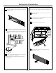
ÉVACUATION À L’EXTÉRIEUR PAR L’ARRIÈRE
(Conduit horizontal)
B
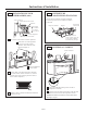
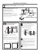
VUE D’ENSEMBLE
DE L’INSTALLATION
B1. Préparation du mur arrière
B3. Fixation de la plaque de montage au mur
B4. Préparation de l’armoire supérieure
B5. Ajustement du ventilateur
B6. Installation du four à micro-ondes
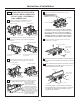
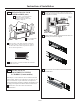
REMARQUES IMPORTANTES :
• Assurez-vous que les vis du moteur du
ventilateur et de la plaque du ventilateur
sont solidement vissées lorsque vous les
remettez en place. Cela évitera les
vibrations excessives.
• Assurez-vous que les fils du moteur sont
bien acheminés, fixés et qu’ils ne sont pas
coincés.
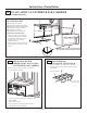
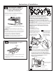
• Lisez les instructions figurant sur le GABARIT POUR
MUR ARRIÈRE.
• Collez-le au mur arrière.
• Percez l’ouverture en suivant les instructions sur le
GABARIT POUR MUR ARRIÈRE.
PRÉPARATION DU MUR
ARRIÈRE POUR L’ÉVACUATION
À L’EXTÉRIEUR PAR L’ARRIÈRE
Vous devez percer une ouverture dans le mur arrière
pour l’évacuation à l’extérieur.
B1.
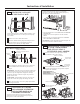
B2.
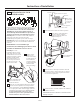
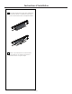
ENLÈVEMENT DE
L’PLAQUE DU VENTILATEUR
Enlevez et conservez la vis qui retient la plaque du
ventilateur au four à micro-ondes. Soulevez la plaque
du ventilateur.
Plaque du ventilateur
Arrière du four
à micro-ondes
B2. Enlèvement de l’plaque du ventilateur
3
/8
"TO
EDG
E
%#
76
+10Ä+(
':*#756#
&#
26
14+5215+6
+10'&176
5+&'
4'%
1/
/'0&'&&
+/'05+10)4'#
5'Ä.#
&'0#+49+..
&+5%*#
4)'+0
6
1*175
'5647%674
'
/
+0+/7/9+&6*4'37+4'&
4'#49#..6'/2.#6'
NOTE
: IT IS
VERY
IMPO
R
TANT TO
READ AND FOLLO
WT
HE
DIRECTIONS
IN THE INSTALLA
T
ION INSTRUCTI
ONS
BE
F
O
RE PR
O
CEEDINGWITH THIS
REAR WALL TEMPLA
T
E.
This R
ea
rWall Te
mpl
ate
se
r
ves to pos
ition the b
ottom
mou
ntin
g plateand to lo
cate the h
oriz
on
ta
l ex
h
au
st
ou
tlet.
1
. Us
e a le
vel
to check
th
at the template
is positioned
a
ccur
ately
.
2. Lo
c
ate a
ndm
ar
k
at le
as
t one
stud
on
thele
ft o
r
r
ight
side o
f the
c
e
n
te
rl
i
ne.
016
'
It is import
ant to u
se
a
t leas
t one wood
scre
w
mou
nted fi
rmly in a s
tud to support the weight
ofth
e micr
ow
ave. Mark
tw
o a
d
di
tional, e
ve
nlyspaced
lo
cations for the s
upplied
to
ggle bolts.
3. Dr
i
ll hole
s in
th
e marked locations.Where t
h
ere is
a s
tu
d
,
d
r
ill a 3/16" hole for woo
d s
cr
ew
s.
For holes
th
at
d
o not lin
e upwith a
s
tu
d, dril
l 5/8
" h
ole
s fo
r
to
gg
le bolts.
016
'
DO NOT
I
NS
T
A
LL THE MOU
NT
I
N
G
P
LATE
AT THISTIME.
4. Re
move th
e te
mplate fromthe
rear wal
l.
5.
Reviewth
e In
sta
llationIns
t
ructi
on book for y
ou
r
installatio
n si
tuat
ion.
Locate and mark holes
to ali
gn wi
th holes
in t
he
mounting
plate.
IMPO
RTANT
:
LO
C
A
T
E AT LEAST ONE STUD ON EITHER
SID
E
OF
THE CENTER
LI
N
E
.
MARKTHE LOCATION F
O
R 2 ADDIT
IONAL, EVENLY
SPACED TOGGLE
BO
LTS
IN THE MO
UN
TING
PLATE
AREA
.
Locate and mar
k holes
to al
ign with holes in the
mountingplate.
IMPO
RTANT:
LOCAT
E AT LEAST ONESTUD
ON EITHER SID
E O
F
THE
CENTERLINE.
MARK
T
HE LO
CATIO
N
F
O
R 2 ADDITION
A
L, EVENL
Y
SP
ACED
TOGGLE
BOLTS IN
THE MOUNTING
PLATE
AREA
.
Trim t
he rear wall temp
late along
the dotted
line.
Trim the rear
wall templat
e alongth
e dotted line.
%
(%76176(14*14+<106#.
1765+&'':*#756
%76*1.'6*4
17)*4'#49
#.
.
(
1
4
':*#
756
#ą
4
12"
4"
Da
rl
ev
ue
lta
ala ho
j
apar
ac
o
nsu
l
t
a
r
la
v
e
rsiónenEs
pa
ñol.
FR-16
IMPORTANT: Ne pas retirer les entretoises
en carton entre l'é cran thermique et la porte.