
Specification Guide

USA
•
10200 David Taylor Drive
•
Charlotte, NC 28262
•
1-800-FRIGIDAIRE
•
frigidaire.com
CANADA
•
5855 Terry Fox Way
•
Mississauga, ON L5V 3E4
•
1-800-265-8352
•
frigidaire.ca
FFGS3026T 07/17
© 2017 Electrolux Home Products, Inc.
INSTALLATION SPECIFICATIONS
•
Product Shipping Weight (approx.) – 220 Lbs.
•
Voltage Rating – 120V / 60 Hz / 5 Amps
•
Amps @ 120V = 5 Amps
•
Always consult local and national electric and gas codes.
•
Make sure wall coverings around range can withstand heat generated by range.
•
Linoleum or any other synthetic floor covering located beneath range, must
be capable of withstanding minimum heat of 90° F above room temperature
without shrinking, warping or discoloring. Insulating pad or 1/4"-thick plywood
required between range and a carpeted floor.
•
Do not obstruct flow of combustion air at oven vent nor around base or
beneath lower front panel of range. Range requires fresh air for proper burner
combustion.
•
Range ships with 3/4" factory regulator.
•
LP Gas Conversion Kit supplied.
•
Gas supply line can enter cabinet through back wall or floor. Recommended
position for gas supply line is located 7" from left cabinet wall and 2" from
floor. Electrical outlet can be located anywhere on the back wall 2" from either
side wall and 12" from floor.Supply line must be equipped with approved
manual shutoff valve, accessibly located in same room as range.
•
Countertop MUST be level in all directions and adjustable range height at least
1/16" greater than tallest cabinet height, to ensure metal rangetop flange will
fit properly on countertop edge.
•
When installing optional Backguard Kit, cutout depth of 21-3/4" minimum /
22-1/8" maximum needs increased to 24".
•
Overhead cabinetry should not exceed a 13" maximum depth.
•
Absolute minimum horizontal distance between overhead cabinets installed
to either side of appliance must be no less than maximum width of appliance.
•
Allow 24" minimum clearance between rangetop and bottom of cabinet
whenbottom of wood or metal cabinet is protected by not less than 1/4"
flame-retardant millboard covered with not less than No. 28 MSG sheet steel,
0.015" stainless steel, 0.024" aluminum or 0.020" copper.
•
Allow 30" minimum clearance when cabinet is unprotected.
•
Allow 5" minimum clearance from edge of rangetop to nearest combustible
wall on either side of unit.
•
To reduce risk of fire when using overhead cabinetry, install range
hood that projects horizontally a recommended minimum of 5" beyond
bottom of cabinets.
COUNTERTOP PREPARATION
Rangetop’s side flanges overlap countertop cutout edges — for detailed
preparation instructions, refer to product installation guide on the web.
•
Flat Square-Finish Countertops – require no preparation since rangetop’s
flange lays directly on countertop edge.
•
Formed Front-Edged Countertops – require front molded edge to be
shaved flat 3/4" from each front corner of opening.
•
Tile Countertops – may need trim cut back 3/4" from each front corner
of opening and /or rounded edge flattened.
•
For existing cutout width greater than 30-1/16" reduce the 3/4" overlap
dimension; for cutout width of 29", replace actual side trim panels with
smaller side trim panels, available with optional Side Trim Kit (refer to
detailed kit installation instructions).
OPTIONAL ACCESSORIES
•
Rear Filler Kit: White – (PN # 901193-9011), Black – (PN # 901193-9010).
•
Side Panel Kit: White – (PN # 903074-9011), Black – (PN # 903074-9010).
•
Backguard Kit: Stainless Steel – (PN # 903046-901S),
White – (PN # 903046-9011), Black – (PN # 903046-9010).
•
Side Trim Kit: White – (PN # 903075-9011), Black – (PN # 903075-9010).
Specifications subject to change. Accessories information available on the web at frigidaire.com / frigidaire.ca
Note: For planning purposes only. Always consult local and national electric, gas and plumbing codes.
Refer to Product Installation Guide for detailed installation instructions on the web at frigidaire.com / frigidaire.ca.
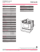
30" Gas Slide-In Range
Baseline
Front
30"
31
1
/2"
35
7
/8"
Adjustable
to
36
5
/8"
5
/8"
25
1
/2"
Overall
depth
including
oven door
in 90° open
position –
47
9
/16"
28
5
/16"
Side
21
3
/4"
Gas
connection
location
(right bottom
rear)
Power cord
location (left
bottom rear)
Locate gas supply line
through back wall or floor
(recommended position)
WALL
5"
min. to nearest
combustible
wall (either side
of unit)
13"
max.
30"
min.
18"
min.
24" min.
1
/2"
min.
30
±
1
/16"
*
Hatched area
should be flat
and leveled
30
±
1
/16"
*
21
3
/4"
min.
22
1
/
8
"
max.
**
1
/2"
min.
35
7
/8"
min.
36
5
/8"
max.
t
Locate cabinet
doors 1" min.
from cutout
opening
1
/4"
min.
24" min. clearance
with protected cabinet bottom
30" min. for unprotected
*Cabinet and countertop
cutout width should match
**24" with optional backguard installed
Locate
electrical outlet
in shaded area
1
1
/2"
max.
Shave raised
edge to clear
space for
31
1
/2" wide
cooktop rim
Front Face of Cabinet
22
7
/8"
min.
23
1
/4"
max.
1
1
/8"
21
3
/4"
min.
22
1
/8"
max.
**
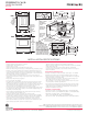
Countertop
Gas & Electric
Supply Installation
Hatched areas are locations
where gas supply line can
enter cabinet. Recommended
position for gas supply line is
located 7" from left cabinet wall
and 2" from floor. Shaded area
is location where electrical outlet
can can be located. Supply line
must be equipped with approved
manual shutoff valve, accessibly
located in same room as range.
Back Wall
Side
Wall
Side
Wall
2" 2"
5"
5"
12"
4"
11"
6"
3"
3"
Floor
2
1
/2"
4
1
/2"
7
1
/2"
30"
Approx.
1
7
/8"
31
1
/2"
(critical)
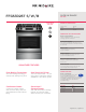
FFGS3026T S / W / B
SLIDE-IN RANGE
30" GAS