
Installation Instructions

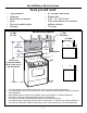

Installation Instructions
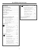
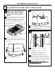
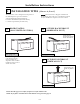
ALIGNING THE WALL PLATE
D.
Area E
Hole A
Hole B
Centerline
notches
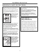
Draw a Vertical Line
on Wall from Center
of Top Cabinet
Draw a horizontal line on wall at the
bottom of “Rear Wall Template”.
Horizontal Line
Horizontal Line
C
L
3/8" TO EDGE
%#76+10Ä+(':*#756#ਸ਼+5
215+6+10'&
1765+&'
4'%1//'0&'&&+/'05+
10)4'#5'Ä.#&'0#+49+..
&+5%*#4)'+061*175'5647%674'
/+0+/7/9+&6*4'37+4'&
4'#49#..6'/2.#6'
NOTE: IT IS VERY IMPORTANT TO
READ AND FOLLOW THE DI
RECTIONS
IN THE INSTALLATION INSTRUCTIONS
BEFORE PROCEEDI
NG WITH
THIS
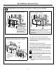
REAR WALL TEMPLATE.
This Rear Wal
l Template serves t
o position the bottom
mounting plate and to locate
the horizontal exhaust
outlet.
1. Use a level to check th
at the template is positioned
accurately.
2. Locate and ma
rk at least one stud on the left or
right side of the centerlin
e.
016'
It is important to use at least one wood
screw mounted firmly in a stud to s
upport the weight
of the microwave. Mark two add
itional, evenly spaced
locations for the supp
lied toggle bolts.
3. Drill holes in the marked locatio
ns. Where there is
a stud, drill a 3/16" hole for
wood screws. For hole
s
that do not line up with a st
ud, drill 5/8" holes for
toggle bolts.
016'
DO NOT INSTALL THE M
OUNTING PLATE
AT THIS TIME.
4. Remove the tem
plate from the rear wall.
5. Review the Installation Instru
ction book for your
installation situation.
Locate and mark
holes to align with h
oles in the
mounting plat
e.
IMPORTANT:
LOCATE
AT LEAST ONE
STUD ON EITHER SIDE OF
THE CENTERLINE.
MARK THE LOCATION FOR 2
ADDITIONAL, EVENLY
SPACED
TOGGLE BOLTS IN
THE MOUNTING PLATE
AREA.
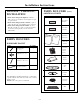
Locate and mark
holes to align with hol
es in the
mounting plat
e.
IMPORTANT:
LOCATE
AT LEAST ONE
STUD ON EITHER SIDE OF
THE CENTERLINE.
MARK THE LOCATION FOR 2
ADDITIONAL, EVENLY
SPACED
TOGGLE BOLTS IN
THE MOUNTING PLATE
AREA.
Trim the rear
wall template al
ong the dotted
line.
%
#
$
%
&
(%76176(14*14+<106#.
1765+&'':*#756
%76*1.'6*417)*
4'#49#..
(14':*#756#ਸ਼
12"
4"
Darle vuelta a la hoja para consultar la
versión en Español.
Draw a vertical line on the wall at the center of the
30" wide space.
NOTE: DO NOT MOUNT THE PLATE AT THIS
TIME.
NOTE: Holes A and B are inside area E. If neither of
important to have at least one wood screw mounted
firmly in a stud to support the weight of the
microwave. Set the mounting plate aside.
1
2
Draw a horizontal line on the wall at the bottom of
“Rear Wall Template”.
Holes A and B are not in a stud, find a stud somewhere
in area E and draw a circle to line up with the stud. It is
3
Find a wall stud in area "E" of mounting plate
Refer to section 1B. Finding the wall studs.
For attaching the mounting plate into stud drill
a 3/16" hole into wood stud. Drill a 5/8" hole for
toggle bolt in 1 other location (Hole A or Hole B)
4
EN-8