
Installation Instructions
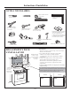

Instructions d’installation
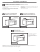
Vos armoires peuvent être dotées de garnitures
décoratives qui entravent l’installation du micro-ondes.
Enlevez l’élément décoratif pour installer convenablement
le four à micro-ondes et pour vous assurer qu’il est de
niveau.
LE FOUR À MICRO-ONDES DOIT ÊTRE DE NIVEAU.
Utilisez un niveau pour vous assurer que le fond de
l’armoire est de niveau.
Si les armoires sont dotées uniquement d’un rebord avant,
sans rebord sur les côtés ou à l’arrière, installez la plaque de
montage plus bas, à la même distance que le rebord avant
de l’armoire. Ainsi, le four sera de niveau.
Mesurez la hauteur intérieure du rebord avant de
l’armoire.
Tracez une ligne horizontale sous le fond de l’armoire,
sur le mur arrière à une distance équivalente à la
longueur intérieure du rebord avant de l’armoire.
Pour l’installation sous une armoire dotée d’un rebord
avant uniquement, alignez les languettes de montage
sur cette ligne horizontale, sans qu’elles touchent le
fond de l’armoire, tel que décrit à l’étape D.
3
2
1
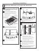
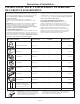
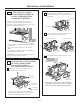
ÉTABLISSEMENT DE L’EMPLACEMENT DE LA PLAQUE MURALE SOUS
VOTRE ARMOIRE
C.
Emplacement de la plaque - sous une armoire
à fond plat
Emplacement de la plaque - sous une
Emplacement de la plaque - sous une armoire
dotée d’un rebord
Au moins 30 po
C
3/
8" TOEDGE
N
O
TE:
I
TI
S
V
ER
Y
I
MPOR
TANT TO
R
E
A
DA
NDFOL
LO
W
THEDIRECT
IONS
INTHE
I
N
S
TALL
A
TION
IN
S
TRU
CTI
O
NS
BEF
OREP
R
OCEED
INGWITH TH
IS
R
E
AR
WALLTEMPLA
T
E.
T
h
is
Rea
rW
a
l
l
T
e
mp
l
ate
serve
sto
p
o
si
tio
n thebo
t
t
om
mount
in
gpl
a
te
andt
o
lo
ca
te th
e
ho
r
iz
o
n
tal
e
x
h
a
u
st
o
u
tl
et.
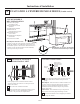
1
.Use a
le
ve
l toc
h
e
c
kt
h
a
t
t
h
etemp
latei
s
po
s
itione
d
a
ccura
tely.
2.Locate and ma
r
kat l
east
o
n
e stu
d onthe
l
eft o
r
rights
id
e
o
f
t
hecenterline.
It is impo
r
ta
nt touse a
tlea
stone wo
o
d
s
cre
w
m
o
un
te
d
firmly
in
a
stu
dto suppo
rtt
he weight
o
f the
microwave. Ma
rk twoadd
i
tio
na
l, evenlyspa
c
e
d
lo
cationsfor t
h
e
supplie
d
t
o
g
g
l
e
b
olt
s
.
3.D
ri
llho
le
s
in
th
em
a
r
kedloc
a
tions.
W
hereth
e
reis
ast
u
d, dr
ill
a
3
/
1
6" holef
o
r
wood
s
cr
e
w
s.
Fo
r
holes
tha
t d
o
no
t lin
e
u
p
wi
tha stud, drill
5
/
8"ho
lesfo
r
t
og
g
l
ebolt
s.
DO N
OT INST
A
LL THEMOU
NT
IN
GP
L
A
TE
AT THI
STIME.
4
.Remove t
hetemp
la
t
e from
th
ere
a
rwa
l
l.
5
.Re
v
i
e
w
t
he
In
s
tallatio
n
In
stru
ct
ionbook for you
r
i
n
stallationsitua
t
ion
.
Locateand m
arkh
oles
t
o
alignwith holes in
t
h
e
mou
nt
ingpla
t
e
.
I
M
P
ORT
ANT:
LO
CATEAT
LE
ASTON
ES
TUD ONEITHER SIDE OF
TH
ECENTERLIN
E.
M
ARK
THELOCATION FOR
2 A
D
D
I
TION
AL,EVENL
Y
SPA
CEDTOGGLE
BOLT
SIN THE
MOUNTI
NGP
LAT
E
AREA.
Locat
e
a
nd
mark holes
to
alignwith holes
in
the
mou
nt
ingplate.
IM
PORTANT:
LO
CATEAT LEAST
ON
ES
TU
D
ON
E
ITH
ER
SI
DEOF
THECE
NTE
RLINE
.
MARKTHE LOC
ATI
ONF
OR
2ADDITIONAL,
E
VENLY
SPA
CED
TOGGLEB
OL
TS
INTHE MOUN
TIN
G
P
LATE
AREA.
T
r
imth
e
rear
w
all
te
mpla
t
ealong t
h
edot
ted
line.
T
r
i
m
the
rear
wall
tem
plate
a
l
ong
thedotted
l
ine.
12"
4
"
Da
r
levueltaa
la
hojapar
acons
ultarla
v
ers
iónen Esp
a
ñol.
16-1/ ″2
Tracez une ligne verticale sur
le mur au centre de l'espace
de 30 po de large.
Tape gabarit pour mur arri
ère
sur le mur correspondant
à la
ligne m
édiane et en touchant
le bas de l'armoire.
C
3/8
"
TO EDGE
NOTE:IT I
S
VERYI
MPO
RT
ANTTO
RE
A
D
A
NDFO
LL
O
W
T
HE
DIRECTI
O
NS
I
NTHE
INST
ALLA
TI
ON INS
TRUCT
I
ONS
BEF
ORE
PROCEE
DINGWI
T
HTHIS
REARWAL
L
T
E
MPLATE
.
Th
isRea
r
Wa
llTemp
l
a
te
ser
ves top
o
sitionthe
b
ot
t
o
m
mo
unti
ngplate a
n
dto l
o
ca
te
the
hor
i
z
o
nt
a
l
e
xhaust
o
u
tlet.
1.
Usea lev
e
l
toche
ck t
h
a
tthe template
i
sposi
t
ion
ed
a
c
c
u
r
ately.
2
.
L
ocat
e
and
ma
r
k
at
l
east o
n
estu
don
t
he le
f
tor
rig
h
t
side
o
fth
e
c
enterline
.
It
i
si
mp
o
r
tan
t t
o
useat l
eas
t
o
n
e
w
ood
sc
re
wmo
u
nt
e
d
fi
r
mly in
a
stu
d
t
o
su
ppor
tthe
we
i
ght
ofthe
m
i
c
row
a
v
e
.Ma
r
k
tw
o a
d
di
tional
,
even
lyspa
ced
l
o
ca
t
ions for
thesupp
l
i
ed
tog
g
l
ebo
l
ts.
3.Drill holes
i
n
t
h
e
m
arke
dl
o
catio
n
s. Wherethere i
s
astud,
d
ri
l
la 3
/16" hol
e
forwood scr
ews.For hole
s
that
do
no
tline up wit
ha stud, dr
i
ll5
/
8" h
ol
es f
or
togg
l
e
bo
l
ts.
D
O
NO
TINSTALL
THEMOUNTING PLATE
AT THIS TIME
.
4.Rem
o
veth
e
t
emp
latefro
m t
h
e
r
earw
a
ll.
5.Revi
ewthe Install
a
ti
onIn
str
u
cti
on
b
oo
k f
oryour
i
n
stall
ati
o
n sit
u
ati
on.
Locat
e andmark
h
ol
es to
ali
gn
wit
h
holes i
n
the
mount
i
ng
plate.
I
MP
ORTAN
T:
L
OCA
T
E
A
T LEAST
ONE
ST
UD ON
EIT
HE
R SI
D
EO
F
THE
CENT
ER
LINE.
MA
R
K THE
L
OC
A
T
IO
N
FO
R
2
AD
DI
TIONAL, E
VE
NLY
SP
A
CE
D
TOGGLEB
OLT
S
I
N TH
E
MO
U
N
T
I
NG PLATE
A
R
EA
.
L
ocateand
markholes t
oa
l
i
gn
w
i
th
holes in the
mount
i
n
g
p
late.
IMPORTANT:
LOCAT
EA
TLE
A
S
T
ON
EST
UD
ON
EITHE
R
SIDEO
F
TH
ECENT
E
R
LINE.
MARKTHE
LOC
ATION
F
O
R2 ADDITIONA
L
, EV
E
NL
Y
SPACEDT
OGGLEBOLTS IN THE MOUNT
ING
PL
AT
E
A
REA
.
Trim
th
e
rear
wa
l
l temp
late
al
on
g the
do
tte
dlin
e.
Trim
t
h
erear w
a
lltemplate al
ong thedo
tt
ed
line
.
12"
4"
Da
rlevu
el
t
a
a
la
ho
ja
pa
raco
n
sult
a
r
la
v
ersió
n
en
Espa
ñol.
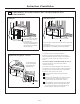
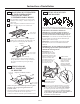
À 30 po de la surface de cuisson
Tracez une ligne verticale sur le mur au centre de l'espace de
30 po de large.
Tape gabarit pour mur arrière sur le mur correspondant à la
ligne m
édiane et en touchant le cadre bas de l'armoire.
C
3/8"
TO
EDGE
N
OT
E
:IT ISVERY IMP
O
R
T
A
NT T
O
RE
A
DA
N
D
FO
LL
O
W T
H
EDIR
E
CTIO
NS
IN
THE
IN
S
T
A
LL
AT
ION
I
NST
R
UC
T
IO
N
S
B
EF
OR
E
P
RO
CEEDING WIT
H T
HIS
R
E
A
R
W
A
LL
T
E
MPL
A
T
E.
ThisRe
arWallTemplate
serv
esto
posit
ion
t
hebott
o
m
mo
un
t
i
n
gplat
e
and
tolo
cat
ethe
h
ori
z
o
nt
al
e
xhaust
o
u
tlet
.
1
.
U
s
e
a
l
evel
t
o
c
h
eckt
hat
t
he
t
e
m
plateispo
s
it
io
ne
d
a
c
c
urat
e
ly.
2
.Loc
at
e
andm
arka
t
le
astone
s
t
udo
nthele
fto
r
ri
g
htsideo
f
t
h
e
ce
nterlin
e.
Itis
im
p
ort
a
ntt
o
u
sea
t
l
east
o
n
ew
o
o
d
screwmo
un
ted
f
ir
mlyina
s
t
ud
to
s
u
p
p
ort
t
heweight
o
fthemicr
o
wa
v
e
.Markt
woa
d
d
itiona
l,
e
venlys
p
ac
ed
loc
at
ion
s
f
or
t
h
e
su
pp
lied
t
ogg
le
b
o
lt
s
.
3
.
D
rillholesin
the
ma
rkedlo
ca
tio
n
s
.Wherethere
is
as
t
u
d
,
dr
ill a3/1
6"
ho
le
f
o
r woods
cre
w
s
.
F
o
rholes
t
hat
d
onotli
n
e
up
w
it
h
a
stud
,d
ri
ll
5/8
"h
ole
s
for
t
og
g
le
b
o
lts.
D
ONOTINS
T
A
LL
T
H
EMOU
N
T
IN
G
PLAT
E
AT
TH
IS
TI
M
E.
4
.
R
em
ove
t
hete
m
p
la
te
fromt
h
e
re
a
r
wal
l.
5.
Re
vi
e
w
t
he
Installa
t
ion
I
n
s
tr
uctionb
o
ok
f
o
r
y
ou
r
installa
t
io
ns
i
t
u
a
t
ion
.
L
o
c
a
tea
n
d
mark
ho
l
e
sto al
ig
n
wit
h
ho
les
i
n the
mo
u
n
tingp
l
ate
.
IMPORTA
N
T
:
LOCATE ATLEAS
T
ON
E
S
TU
D ONE
I
T
H
E
R
SIDE OF
THE
C
ENTER
LIN
E.
MARKTH
E L
OC
AT
IONFOR
2
ADDIT
I
O
NA
L,EV
E
NLY
SP
A
C
ED
TOG
GLE
B
OL
TS INTHEMO
U
N
T
ING P
L
A
TE
A
REA.
Locate a
n
d
ma
rk
h
oles to
a
lignw
ith holesi
n
t
h
e
mounti
ng p
l
ate.
IMPO
R
TA
N
T:
LOCATE
A
TL
E
AST
ONEST
U
DON EITH
E
R SI
D
E OF
T
H
ECENT
ER
L
IN
E
.
MA
RK
THE L
OC
ATION
F
OR
2
AD
D
I
TIONAL
,
EVE
NL
Y
S
P
ACED T
O
GG
L
E BOLT
S
IN
TH
E MO
U
NTING P
L
ATE
AREA
.
T
r
imtherear
w
a
ll te
m
p
latealongthe
dotte
d lin
e.
Trim
therea
r
wa
ll
te
m
p
l
a
te
alo
n
g
th
e
d
o
tte
dlin
e
.
12"
4
"
D
a
r
levu
e
ltaa
la
h
o
ja
paraco
n
s
u
l
t
a
r
la
v
ersi
ó
ne
n
E
s
pañ
o
l.
3/8
"TO EDGE
N
O
TE:
I
T ISVERY IMPOR
T
AN
T T
O
R
EAD
AND
FO
L
LO
W THE D
IRECTION
S
IN THE INST
ALL
ATIONINST
RUCTIONS
BEFOREPROCEEDIN
GWITH THI
S
R
EAR WALL T
EMPL
AT
E.
This
R
ear
W
all Template servesto p
os
it
i
o
n
thebot
tom
mo
u
ntin
g plat
e
andto loc
ate the ho
rizon
tal exha
us
t
outle
t.
1. Use al
ev
el to chec
kth
at the te
mpla
te isposition
ed
accur
a
te
ly.
2.Loc
ate an
d
markat lea
st one stud
o
n
t
he left or
r
ig
ht
sid
e
o
f
the ce
n
te
r
lin
e.
It is important t
o
us
e a
t le
a
s
t o
ne
wo
od
scr
e
w
mo
u
nted fir
mly in a stu
d
to
support the we
ig
h
t
ofthe microw
a
v
e. Ma
rk two
a
d
d
itional, evenl
ys
p
ace
d
lo
cation
s for the supp
lie
d toggle bolts.
3.Drill hole
s in
t
hemar
k
ed
locations.
Where there is
a s
tu
d, dr
i
lla 3
/16" holefo
r wood s
crews
. Fo
r
ho
le
s
th
a
t do no
t lin
e u
p with a st
u
d,drill 5
/8" h
ole
s fo
r
toggle bo
lts
.
DO NOT INSTA
L
L
TH
E
MO
U
N
TIN
G
PL
ATE
AT TH
IS TIME.
4
.
Remove
th
e te
mp
late from
t
herear w
a
ll.
5.Re
v
ie
w the Ins
ta
ll
atio
n In
stru
c
tionboo
k fo
ryour
in
stalla
tion
s
ituation.
Lo
cate an
dmark holes to alig
n w
it
h
holesin the
mounting pl
a
t
e.
IMPO
R
T
ANT:
LOC
ATE ATLEAST
ONE ST
U
D
ON
EI
THERSI
D
E
OF
THE C
ENTER
LIN
E.
MAR
K
THELOCATION
FO
R
2
AD
DI
TIONAL, EVEN
L
Y
SPACED TOGGLE BO
L
T
S
I
NTH
EMOUNTIN
G
PLATE
AR
EA
.
Locate an
dma
rk
holes to align wit
hh
ol
esin the
mountin
g pl
ate.
IMPO
RTANT:
LOCAT
E AT LEAST
ONE STU
DON EI
TH
ERSIDE OF
THE CENTERLINE
.
MARKT
HE
LO
C
ATIONF
O
R2 AD
DITI
ON
AL, EVENLY
SPA
CED T
O
G
GLEBO
L
TS
I
NTHE MO
UNTING PLAT
E
AR
EA.
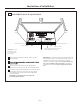
Trim there
arwall template along the dotted
line.
Trim
th
e
rearwall tem
plate
a
l
ong
the
dotted
line.
12
"
4"
Darle
v
u
el
t
a
a
laho
ja
para
con
s
ult
a
rla
v
e
r
sió
nen
Españo
l.
À 30 po de la surface de cuisson
Tracez une ligne sur
le mur arrière égale à
la profondeur de le
surplomb avant
FR-7