
Electrolux Twins Trim Kit Resource Guide


P/N: A21568901
Installation Instructions for
Single-Door Freezer and Refrigerator Pairing Kit
An authorized service technician is recommended to install the filtered ice kit.
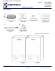
Components
Contains:
Part Part number Qty.
A Heater Assembly: 12V 10W 14.4Ω , Aluminum foil sandwich,
PVC wire insulation, Acrylic adhesive, 5.5 mm x 2.5 mm
barrel connector spliced in heater assembly
A21442901 1
B AC Power Cable: Ultra low profile 6ft NEMA 5-15P to C13
Angled Power Cord, 3 pin plug
A21545701 1
C Power Supply: 12V 60W AC/DC Adapter, 5.5mm x 2.5mm x
10.5 mm plug connector
A21545401 1
D Double-sided Tape 316237303 2
E Clips 218990901 6
Recommended Tool: Gloves
IMPORTANT
Make sure there are two separate outlets for the freezer and the refrigerator as
specified in IMPORTANT SAFETY INFORMATION in the Use & Care Manual.
Installation
Before cleaning your appliance, turn o power to your appliance by unplugging the power
cord from the electrical outlet. Wipe down both sides of the refrigerator and the freezer.
NOTE
Never use CHLORIDE to clean stainless steel. Clean stainless-steel front and handles
with non-abrasive soapy water and a dishcloth. Rinse with clean water and a soft
cloth. Wipe stubborn spots with an ammonia-soaked paper towel, and rinse. Use a
non-abrasive stainless-steel cleaner, such as Frigidaire ReadyClean™ Stainless Steel
Cleaner found on Frigidaire.com. Always follow the manufacturer’s instruction
NOTE
Always, clean, wipe and dry with the grain to prevent scratching. Wash the rest of
the cabinet with warm water and mild liquid detergent. Rinse well and wipe dry with
a clean soft cloth.
CAUTION
The cabinet is heavy. Two people are recommended to lift or move the cabinet.
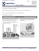
1. If you use the dual installation trim kit,
install the levelers on the units before
installing the heater (Fig. 1).
NOTE: Please refer to “U19 All Refrigerator
and All Freezer Trim Kit Installation
Instruction (A00343903--page 9 Fig, 9) for
further trim kit installation instruction.
Fig. 1
X X
X X
X
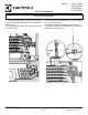
NOTE: Use gloves for the next step.
2. Peel o the paper backing from the
first heater.
3. Adhere the first heater to the lower
right side of the left-side unit (0.5in
from the bottom and 0.5in from the
back wall) so the harnesses come out
at the top.
NOTE: Make sure you adhere the heater
completely with no air pockets (Fig. 2A).
4. Peel o the paper backing from the
second heater.
5. Adhere the second heater to the
upper left side of the right-side unit
(0.5in from the top and 0.5in from the
back wall) so the harnesses come out
at the bottom.
NOTE: Make sure you adhere the heater
completely with no air pockets (Fig. 2B).
NOTE: For the best results, please
use the configurations of the heaters
mentioned (Freezer- bottom right side and
Refrigerator top left side).
Avoid:
Both heaters on the Freezer
Both heaters on the Refrigerator
Both heaters on the top
Both heaters on the bottom
Both heaters in the center
8. If the power supply cannot be placed
on top of the unit, adhere it vertically
on the back wall of the unit and make
sure the connection of the 3-prong
connector to the power supply is
facing down (Fig. 5).
NOTE: You cannot feel the
heater temperature.
Fig. 5
9 Push the two units together.
10. Use the clips provided to hold the
excess power cords to the back of the
units such that all wires are away from
the floor (Fig. 6).
NOTE: Make sure the harnesses and cables
are cleared o the floor before the units are
pushed back in place. This will prevent any
damage to the wires.
NOTE: The location of clips shown is
an example.
11. Plug the power supply into the main
outlet before pushing the units into the
final position.
12. Units can now be installed.
Fig. 6
Final Checklist
Wipe down units
Heater 1 on bottom right side of the freezer
Heater 2 on top left side of the refrigerator
Heater plugged into power supply
Power supply adhered to desired position
Power cables held away from the floor with the help of clips
Power supply plugged into the outlet and green LED on
A
B
C
D
E
Fig. 2
.5"
.5"
.5"
.5"
A B
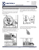
NOTE: Confirm the power supply fits into
the cutout when placed on top of the unit.
Also confirm the power supply reaches the
power outlet when placed on top of the
unit (Fig. 4A).
7. Apply the 2 strips of double-sided tape
to the power supply and adhere the
power supply on top of the unit (Fig. 4B).
Fig. 4
A
B
6. Plug in the connector of the two
heaters (A) into the power supply (B)
(Fig. 3).
Fig. 3
A
B