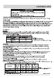
Packaged Terminal Air Conditioner 13-14 2 2 3 15 16 4 5-7 8-10 11-12 1-866-942-1567 17 18 19 (Dec.
SAFETY CONSIDERATIONS Recognize safety information. This is the safety-alert symbol . When you see this symbol on the unit and in instructions or manuals, be alert to the potential for personal injury. Understand these signal words: DANGER, WARNING, and CAUTION. These words are used with the safety-alert symbol. DANGER identifies the most serious hazards which will result in severe personal injury or death. WARNING signifies hazards which could result in personal injury or death.
UNIT FEATURES This unit has many exciting features which are different from those found on standard PTAC models. The owner must be familiar with these features in order to fully understand the operation and capability of the unit. Intelligence -- Your unit has an on board computer that utilizes real time diagnostics to prolong the life of your unit. There is an LED indicator on the control board, behind the front panel, that will flash an error code if the unit has detected some kind of faulty condition.
INSTALLATION Proper installation is the responsibility of the installer. Product failure due to improper installation is not covered under Warranty. CHASSIS INSTALLATION When units are shipped with a sleeve: 1.Remove shipping tape if they are applied. 2.Remove front panel. See Fig.10. 3.Unscrew four screws which connect the main unit with sleeve. The screws location can be referred to Fig.11. 4.Pull out the unit from the wall sleeves. 5.
INSTALLATION RETROFIT SLEEVE PREPARATION IMPORTANT: Inspect wall sleeve thoroughly prior to installation. Manufacturer does not assume responsibility for costs or damages due to defects in sleeve or for improper installation. ! !WARNING WARNING ELECTRICAL SHOCK HAZARD Failure to follow this warning could result in personal injury or death. Disconnect all power to unit to avoid possible electrical shock during installation.
INSTALLATION INSTALLATION OF A FRIGIDAIRE PTAC INTO A FRIGIDAIRE WALL SLEEVE 1. Carefully remove shipping tape from the front panel and vent door. See Fig. 8. 2. Remove shipping screw from the vent door, if present. See Fig. 9. 3. Remove front panel. See Fig. 10. 4. Lift unit level and slide unit into wall sleeve until foam seal rests firmly against front of wall sleeve. 5. Secure with four screws (supplied) through the unit flange holes. See Fig. 11. 6. Reinstall front panel. See Fig. 12.
SYSTEM CONFIGURATION VENTILATION CONTROL The ventilation control lever is located at left side of unit, behind the front panel. NOTE: The vent door shipping screw must be removed before using vent control lever. See Installation Instructions. When set at CLOSE, only the air inside the room is circulated and filtered. When set at OPEN, outdoor air will be drawn into room. Energy Tip: Keep the vent control at CLOSE. Room air will be filtered and circulated.
SYSTEM CONFIGURATION DIP SWITCHES Auxiliary dip switch controls are located behind the front panel, through an opening below the control panel. To access, remove front panel. See Fig. 10. Dip switches are accessible without opening the control box. Unit must be powered OFF to effectively change their status. Factory settings for dip switches will be in the DOWN position. See Table 4 - Dip Switch Functions for functions of each dip switch position. Dip Switches Fig.
SYSTEM CONFIGURATION KEYPAD CONFIGURATION Keypad Configuration You can customize your unit additionally using the keypad configuration options. To enter Keypad configuration Connect the unit to power. Press and hold the "fan speed " and the "V " for 5 continuous seconds, within 30 seconds of the unit being powered up. If the unit has had power for more than 30 continuous seconds, keypad configuration cannot be made.
AUXILIARY CONTROLS WALL THERMOSTAT TERMINAL IMPORTANT: Only trained, qualified personnel should access the electrical panel on unit and install electrical accessories. Please contact your local electrical contractor, dealer, or distributor for assistance. Thermostat Wire Routing Thermostat wire is field supplied. Recommended wire gauge is 18 to 20 gauge solid thermostat wire. R W Y O Gh Gl C THERMOSTAT WIRE ROUTING (UNDER SLEEVE, BEHIND FRONT PANEL) Fig.
AUXILIARY CONTROLS TERMINAL CONNECTIONS The wall thermostat terminal block is located behind the front panel and is easily accessible on front of control panel. Energy management (24VAC in) Common R W Y TYPICAL WALL THERMOSTAT O See Note 1 GH GL C See Note 2 STATUS LED NOTES: 1. Use terminal “O” for heat pump connection only. 2. Terminal “C” (common) is typically only required for digital thermostats. TERMINAL BLOCK Energy Management Terminal Connections Wall Thermostat Terminal Connections Fig.
SAFETY PRECAUTIONS SAFETY PRECAUTIONS DANGER! Avoid Serious Injury or Death 1. Do not attempt to install air conditioner by yourself. 2. This air conditioner contains no user-serviceable parts. Always call an authorized Electrolux servicer for repairs. 3. When moving the air conditioner, always call an authorized Electrolux servicer for disconnection and re-installation. 4. Do not insert or place fingers or objects into the air discharge area in the unit. 5.