All about the Installation of your Split Type Room Air Conditioner Model(indoor/outdoor): FRS093LW1/FRS093LC1 FRS123LW1/FRS123LC1 www.frigidaire.com USA 1-866-942-1567 www.frigidaire.
Safety precautions This appliance must be installed by a qualified licensed HVAC technician in accordance with all applicable codes. All electrical connections should be performed by a licensed electrician. DANGER! Avoid Serious Injury or Death 1. Do not attempt to install the split air conditioner by yourself. 2. This air conditioner contains no user-serviceable parts. Always call an authorized Electrolux servicer for repairs. 3.
To prevent injury to the user or other people and property damage, the following instructions must be followed. Incorrect operation due to ignoring of instructions may cause harm or damage. The seriousness is classified by the following indications. 1. Connect with the power properly. Otherwise, it may cause electric shock or fire due to excess heat generation. 2. Always ensure effective grounding. No grounding may cause electric shock. 3.
11.Do not open the unit during operation. It may cause electric shock or injury. 12.Do not drink water drained from air conditioner. It contains contaminants and could make you sick. 13.Do not disassemble or modify unit. It may cause failure of appliance and electric shock. 14.When the air filter is to be removed, do not touch the metal parts of the unit. It may cause an injury. 15.When the unit is to be cleaned, switch off, and turn off the circuit breaker.
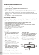
Choosing the installation site Installation Warnings 1. Carefully read the installation manual before beginning. 2. Follow each step as shown. 3. Observe all local, state and national electric codes. This appliance must be installed by a qualified licensed HVAC technician in accordance with all applicable codes. All electrical connections should be performed by a licensed electrician. 4.
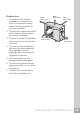
Outdoor Unit More than 1 feet 1. The outdoor unit must be installed at a convenient site that is not exposed to strong winds. The site should be dry and well ventilated. More than 2 feet More than 1 feet 2. The site must support the weight of the outdoor unit and allow for vertical installation. 3. There must not be the possibility of increased noise and vibration at the site. More than 6.6 feet More than 2 feet 4.
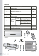
Parts list NUMBER PART NAME QTY .
1 More than 6" 2 3 Indoor unit More than 5" 6 More than 5" 6 Air filter 7 8 More than 2 feet More than 1 feet A 10 9 More than 2 feet 4 5 B C More than 6.6 feet Outdoor unit Attention 1. This illustration is for explanation purposes only. 2.
11
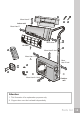
6" or more from the ceiling Installation plate 10.72" Refrigerant pipe hole (left) Ø 2.56" 3.55" 1.77" 1.77" 1.77" 5" or more from the wall 11.54" Indoor unit outline 3.15 5" or more from the wall Refrigerant pipe hole (right) Ø 2.56" 19.27" 36.25" (B) Capacity < 12000 Btu's Fixing the Installation Plate 1. Install the installation plate horizontally over the structural parts on the wall using the spaces indicated on the plate, as shown in the figures above. 2.
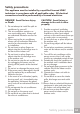
Connective pipe and drainage installation Connective pipe 1. For the left-hand and right-hand piping, remove the pipe cover from the side panel. The pipe cover must be kept as it may be used when relocating the air conditioner to any other place. Pipe cover (right) Drainage 1. Run the drain hose sloping downward. Do not install the drain hose as illustrated sideward. 2.
3. Piping can easily be made by lifting the indoor unit with a cushioning material between the indoor unit and the wall. Get it out after finish piping. 4. Push the lower part of the indoor unit up on the wall, Then move the indoor unit from side to side, up and down to check if it is hooked securely. Piping and wrapping 1. Bundle the tubing, connecting cable, and drain hose with tape securely and evenly as shown in the sideward figure. 2.
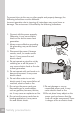
Outdoor unit installation 1. Install the outdoor part of the unit on a rigid surface to avoid excess noise and vibration. 2. Direct the air vent toward an area without obstacles. 3. Install the unit at the site where it is exposed to as little wind as possible, especially in areas where it is frequently windy. 4. If the installation site is exposed to heavy winds, such as in coastal areas, place the unit along the widest part of the wall or use protective plates. 5.
A Settlement of outdoor unit Anchor the outdoor unit tightly and horizontally on a concrete or rigid mount with a bolt and nut 0.39 inch or 0.32 inch diameter (Purchasedy separately). Air inlet Air inlet B Air outlet A (inch) B (inch) 2.30'x1.76'x0.77' 1.50' 0.82' 2.25'x1.41'x0.85' 1.51' 0.91' 2.56'x1.77'x0.82' 1.80' 0.91' 2.49'x1.94'x0.94' 1.74' 0.95' 2.77'x2.28'x1.10' 1.84' 1.
Refrigerant piping connection Unit comes with 16.4 feet tubing bundle. It is not recommended to cut. If too long, loop for excess. Note: Keep original bend so not kinking of the tube occurs. Flaring work Main cause for refrigerant leakage is due to defect in the flaring work. Pipe Carry out correct flaring work using the following procedure: 1. Cut the pipes and the cable. A) Use the piping kit accessory or pipes purchased locally. B) Measure the distance between the indoor and the outdoor unit.
4. Flaring work. Firmly hold copper pipe in a die in the dimension shown in the table below. OUTER DIAMETER (inch) Bar Copper pipe Handle A (inch) Max. Min. 1/4 0.051 0.028 3/8 0.063 0.039 1/2 0.071 0.039 5/8 0.095 0.087 Connection Adjustment 1. Align the pipes to be connected. 2. Screw the flare nut with your fingers, and then tighten it with a spanner and torque wrench, as shown in the following figure.
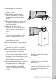
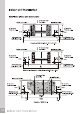
Connect the cable to the indoor unit 1. The inside and outside connecting cable can be connected without removing the front grille. 2. Connecting cable between indoor unit and outdoor unit shall be approved polychloroprene sheathed flexible cord, type designation 16AWG or heavier cord. 3. Lift the indoor unit panel up, remove the electrical box cover by loosening the screw. 4. Ensure the colour of wires of outdoor unit and the terminal Nos. are the same to the indoors respectively. 5.
9000 and 12000 Btu's COOLING MODEL 9000 and 12000 Btu's HEATING AND COOLING MODEL Terminal block of indoor unit 1 2 3 "Connector A" or "Connector B" Terminal block of indoor unit 4 1 2(N) 3 4 1 2(N) 3 4 or To Outdoor Unit To outdoor unit 18000 Btu's HEATING AND COOLING MODE "Connector A" Terminal block of indoor unit To outdoor unit 21 Electrical work To outdoor unit
Connect the cable to the outdoor unit 1. Remove the electrical control board cover from the outdoor unit by loosening the screw. 2. Connect the connective cables to the terminals as identified with their respective matched numbers on the terminal block of indoor and outdoor units. The connective cable to power supply shall be approved polychloroprene sheathed flexible cord. 3. Secure the cable onto the control board with the cord clamp. 4.
9000 and 12000 Btu's COOLING MODEL 9000 and 12000 Btu's HEATING AND COOLING MODEL "Conector A" or "Conector B" Terminal block of outdoor unit Terminal block of outdoor unit L N G 1 2 3 4 1 2(N) 3 1 4 Cables board "Conector C” or "Conector D” Terminal block of outdoor unit To indoor unit 1 2(N) 3 1 2(N) 3 4 Cables board 18000 Btu's HEATING AND COOLING MODEL "Conector A" or "Conector B" Terminal block of outdoor unit o Cables board 23 Electrical work 2(N) 3 Cables board Cord clamp
Caution After the confirmation of the above conditions, prepare the wiring as follows: 1. Never fail to have an individual power circuit specifically for the air conditioner. As for the method of wiring, be guided by the circuit diagram posted on the inside of control cover. 2. The screws which fasten the wiring in the casing of electrical fittings are liable to come loose from vibrations to which the unit is subjected during the course of transportation.
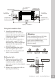
Air purging with vacuum pump 1. Check that each tube(both liquid and gas side tubes) between the indoor and outdoor units have been properly connected and all wiring for the test run has been completed. Remove the service valve caps from both the gas and the liquid side on the outdoor unit. Note that both the liquid and the gas side service valves on the outdoor unit are kept closed at this stage. 2. When relocating the unit to another place, perform evacuation using vacuum pump. 3.
When using the vacuum pump For method of using a manifold valve, refer to its operation manual. 1. Completely tighten the flare nuts at connection point A, B, C and D. Connect valve core removal tool to the charging port, then connect vacuum hose to valve core tool. Open the schrader valve. Note: The schrader valve is inside the charging port. 2. Connect the other charge hose of manifold valve to the vacuum pump. 3. Fully open the handle Lo of the manifold valve. 4. Operate the vacuum pump to evacuate.
Electrical safety Perform the electric safety check after completing installation: 1. Insulated resistance: The insulated resistance must be more than 2M . 2. Grounding work: After finishing grounding work, measure the grounding resistance by visual detection and grounding resistance tester. Make sure the grounding resistance is less than 4 . 3.
Test running Perform test operation after completing gas leak check at the flare nut connections and electrical safety check. 1. Connect the power, press the ON/OFF button on the remote controller to turn the unit on. 2. Use the MODE button to select COOL, HEAT(Only for models with heating function), AUTO and FAN to check if all the functions work well. 3.
Preparing the device for operation 1. Contact a specialist to install the device. 2. Guarantee that the unit is appropriately fastened and complies with all of the aforementioned safety norms. 3. Before operating the air conditioner, ensure that the air filter is installed correctly. 4. If the unit has been out of use for a long period of time, it is recommended that the air filter be cleaned before use. During continuous use, clean the air filter every two weeks. 5.