
Installation Guide

7
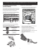
30” ELECTRIC FRONT CONTROL FREESTANDING INSTALLATION INSTRUCTIONS
3-Wire and 4-Wire Permanent
Connection
This appliance may be connected by means of permanent
wiring.
When installing permanent wiring, do not leave excess
wire in range compartment. Excess wire in the range
compartment may not allow the rear access cover to be
replaced properly and could create a potential electrical
hazard if wires become pinched. Connect only as
instructed. When using exible conduit or range cable use
ex connector or range cable strain relief.
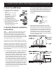
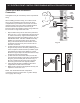
1. Strip insulation away from the ends of the permanent
wiring for Line 1, Line 2, Neutral (also strip ground wire
on 4-Wire Connections). Tighten all wire leads to the
terminal block (Follow wire locations shown in Fig. 16).
IMPORTANT NOTE: DO NOT LOOSEN the factory
installed nut connections which secure the range
wiring to the terminal block. Electrical failure or loss
of electrical connection may occur if these nuts are
loosened or removed.
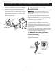
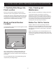
2. (4-Wire Permanent Connection ONLY) Disconnect
the ground strap. Remove the factory installed ground
screw and plate to release the factory installed copper
ground strap from frame of the appliance. Cut and
discard the copper strap from the terminal block. Keep
the ground screw and ground plate.
3. (4-Wire Permanent Connection ONLY) Connect the
ground wire lead (Green) to the frame of the appliance
using the ground screw & plate as shown in Fig. 17.
Be sure to install using the same hole in the frame
where the ground screw was originally installed.
4. Follow the manufacturer’s installation instructions
supplied with the strain relief and install.
5. Make sure all connections are tightened securely and
replace the rear access cover.
NOTE: Non-terminated eld wire compression
connections must be set at 22 in./lbs. or greater. Always
use 10 gauge wire or larger.
Fig. 16
Fig. 17
L1
NEUTRAL
L2
Ground screw
and ground plate
Ground
strap
Tighten
all leads