
Installation Guide

6
GAS WALL OVEN INSTALLATION INSTRUCTIONS
3. Provide an Adequate Gas
Supply
Important: Read these instructions carefully before
connecting this unit to a gas supply.
The units covered in these instructions are designed
to operate on natural gas at 4" of manifold pressure
or on LP gas at 10" of manifold pressure.
A convertible pressure regulator is connected in
series with the manifold of the wall oven unit and
must remain in series with the supply line, regardless
of which type of gas is being used.
For proper operation, the maximum inlet pressure to
the regulator must not exceed 14" of water column
(W.C.) pressure.
To check the regulator, the inlet pressure must be
at least 1" (or 3.4 kPa) greater than the regulator
pressure setting. If the regulator is set for 4", the
inlet pressure must be at least 5". If the regulator
is set for 10", the inlet pressure must be at least 11".
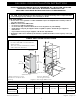
A manual shut-o valve must be installed on the gas
supply line external to the unit and where it can be
easily reached for the purpose of turning the gas
to the unit on and o. The recommended location
for the shut-o valve is in the cabinet beneath the
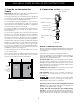
installation cutout (see Figure 7).
The gas supply line to the unit should be ½" (1.3 cm)
or ¾" (1.9 cm) pipe.
Close all openings in the cabinet cavity that encloses
this unit. All openings around gas service outlets
must be closed at the time of installation.
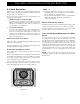
10" Min
(25.4 cm
Min)
27 ½" Max
(69.9 cm
Max)
Figure 7
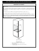
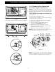
4. Connection to Gas (see figure 8)
IMPORTANT: A pipe joint sealant resistant to
the action of LP Gas must be used on all pipe
connections.
Do not use a flame to check for leaks
from gas connections. Checking for leaks with a
flame may result in a fire or explosion.
Disconnect the oven and its individual shutoff
valve from the gas supply piping system during any
pressure test greater than ½ psig.
Isolate the wall oven from the gas supply piping
system by closing its individual manual shuto valve
during any pressure testing of the gas supply piping
system at test pressures equal to or less than ½ psig.
BEFORE CONNECTING THE UNIT
Remove all packing material and literature from wall
oven before connecting gas and electrical supply to
the appliance.
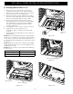
Open the oven storage compartment door.
The fuel regulator on this appliance has a built-in
shut-o valve. Make sure the valve is UP in the OPEN
position (see Figure 9b and 9c).
Check for leaks. After connecting gas, check system
for leaks with a manometer. If a manometer is not
available shut all pilots o (if present), turn on the
gas supply to the unit and use a liquid leak detector
at all joints and connections.
Tighten all connections if necessary to prevent gas
leakage in the wall oven or supply line.
Figure 8
Shut-O Valve
Pressure Regulator
Adaptor or Union
Solid Pipe or
Flex Connector
Cabinet Base
External Shut-O
Valve