Models PL30WC51EC PL36WC51EC PL42WC51EC ENGLISH.....................................2 FRANÇAIS................................
READ AND SAVE THESE INSTRUCTIONS ! INTENDED FOR DOMESTIC COOKING ONLY ! WARNING TO REDUCE THE RISK OF FIRE, ELECTRIC SHOCK, OR INJURY TO PERSONS, OBSERVE THE FOLLOWING: 1. Use this unit only in the manner intended by the manufacturer. If you have questions, contact the manufacturer at the address or telephone number listed in the warranty. 2. Before servicing or cleaning unit, switch power off at service panel and lock service panel to prevent power from being switched on accidentally.
OPERATION Controls The hood is operated using the (4) push-buttons located at eye-level, on the front edge of the hood. The light switch turns the halogen lamps on and off. The blower on-low / off switch turns the blower on to its lowest running speed. The blower must be turned on using this switch. Turn the blower off by pressing this switch a second time.
PREPARE THE HOOD Unpack hood and check contents. You should receive: 1 - Hood 1 - Decorative Flue Assembly 1 - Parts Bag containing: 1 - Mounting Bracket 1 - Discharge Collar 1 - Flue Mounting Bracket 8 - Mounting Screws (4,8 x 38mm Pan Head) 4 - Mounting Screws (3,9 x 9,5mm Pan Head) 2 - Mounting Screws (3.9 x 6mm Flat Head) 8 - Drywall Anchors 1 - Installation Instructions DISCHARGE COLLAR MOUNTING BRACKET 4 MOUNTING SCREWS (3.9 x 9.5mm Pan Head) 2 MOUNTING BRACKET SCREWS (3.
INSTALL THE DUCTWORK (DUCTED HOODS ONLY) ! ROOF CAP 6” ROUND DUCT CAUTION: To reduce the risk of fire, use only metal ductwork. 1. Decide where the ductwork will run between the hood and the outside. 2. A straight, short duct run will allow the hood to perform most efficiently. 3. Long duct runs, elbows, and transitions will reduce the performance of the hood. Use as few of them as possible. Larger ducting may be required for best performance with longer duct runs. 4. Install a roof or wall cap.
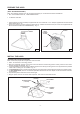
INSTALL FLUE MOUNTING BRACKET (DUCTED AND NON-DUCTED HOODS) 1. Assemble the flue mounting bracket, adjusting outside width as shown. See Figure 7. 2. Carefully center the mounting bracket directly over the range hood location. 3. Secure the bracket assembly to the ceiling using (2) 4.8x38mm mounting screws and drywall anchors (Fig. 8). Make sure the bracket is pushed into the corner, tight against the wall and centered over the hood. FLUE MOUNTING BRACKET DRYWALL ANCHORS 3.
PREPARE THE HOOD (NON - DUCTED HOODS ONLY) Note: The following materials must be purchased separately for non-ducted recirculation installations. • Non - Ducted Recirculation Kit, Model DFKTWC51EC. • 5” diameter metal duct. 1. Discard discharge collar and damper supplied with the hood. Install the 5” to 6” adapter supplied with the Non-Ducted Recirculation Kit. Fig. 10. 2. Secure the plenum to the flue mounting bracket with (2) 3.
INSTALL THE HOOD, cont’d 8. Carefully place the decorative flue on the hood. Fig. 13. - On ducted installation in rooms with 8-foot ceilings, the air vents are concealed. Install the flue with the air vents down. - On non-ducted installations in rooms with 8-foot ceilings, the air vents are exposed. Install the flue with the air vents up. - On ducted and non-ducted installations in rooms with 9-foot ceilings, the vents are exposed. Install the flue with air vents up.
SERVICE PARTS - LISTE PIECES DE RECHANGE MODELS PL30WC51EC - PL36WC51EC - PL42WC51EC KEY No. DESCRIPTION (ENGLISH ) N.
SERVICE PARTS - LISTE PIECES DE RECHANGE MODELS PL30WC51EC - PL36WC51EC - PL42WC51EC - 19 -