
Installation Guide


2
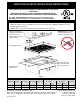
induction cooKtoP inStALLAtion inStRuctionS
H
G
F
L
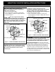
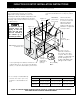
Figure 2 – COUNTERTOP CUTOUT OPENING
CAUTION
To eliminate the risk of
burnsorrebyreachingoverheated
surfaces,cabinetstoragespacelocated
abovethecooktopshouldbeavoided.
Ifcabinetstorageisprovided,riskcan
bereducedbyinstallingarangehood
thatprojectshorizontallyaminimumof
5"(12.7cm)beyondthebottomofthe
cabinets.
* Letters on this figure refer to chart
on front page except for J and K.
OverheadCabinetShouldNotExceeda
MaximumDepthof13"(33cm)
30"(76.2cm)Min.Clearance
BetweentheTopofthe
CookingPlatformandthe
BottomofanUnprotected
WoodorMetalCabinet
24"(61cm)Min.whenBottom
ofWoodorMetalCabinet
isProtectedbyNotLess
Than1/8"(0.3cm)Flame
RetardantMillboardCovered
WithNotLessThanNo.28
MGSSheetSteel,0.015"(0.4
mm)StainlessSteel,0.024"
(0.6mm)Aluminumor0.020"
(0.5mm)Copper.
2½"(6.4cm)Min.From
EdgeofCutouttoFront
EdgeofCountertop
Approximate Location of
JunctionBox
18"
(45.7cm)
It is not recommended to use
drawer underneath cooktop.
Emptyspaceisneededfor
installation purpose.
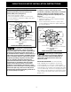
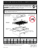
J Min.FromEdgeof
CooktoptoNearest
CombustibleWall
(EitherSideofUnit).
12"
(30.5cm)
10"
(25.4cm)
Min.
K Min.Recommended
DistanceBetweenRear
EdgeofCutoutand
NearestCombustible
SurfaceAbove
Countertop
24"
(61cm)
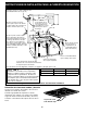
Model and Serial Number Location
The serial plate is located under the cooktop.
When ordering parts for or making inquires about
yourcooktop,alwaysbesuretoincludethemodel
and serial numbers and a lot number or letter from the
serialplateonyourcooktop.
Serial plate is located
under the burner box
of cooktop.
MODEL J K L
30" 2" (5.1cm) 11/2"(3.8cm) 30"(76.2cm)
36" 2" (5.1cm) 2" (5.1cm) 36"(91.4cm)