Model PL36PC50EC ENGLISH.....................................2 FRANÇAIS................................
READ AND SAVE THESE INSTRUCTIONS ! INTENDED FOR DOMESTIC COOKING ONLY ! WARNING TO REDUCE THE RISK OF FIRE, ELECTRIC SHOCK, OR INJURY TO PERSONS, OBSERVE THE FOLLOWING: 1. Use this unit only in the manner intended by the manufacturer. If you have questions, contact the manufacturer at the address or telephone number listed in the warranty. 2. Before servicing or cleaning unit, switch power off at service panel and lock service panel to prevent power from being switched on accidentally.
OPERATION Controls The hood is operated using the (4) push-buttons located at eye-level, on the front edge of the hood. The light switch turns the halogen lamps on and off. The blower on-low / off switch turns the blower on to its lowest running speed. The blower must be turned on using this switch. Turn the blower off by pressing this switch a second time.
PREPARE THE HOOD Unpack hood and check contents. You should receive: 1 - Hood 1 - Decorative Flue Assembly 1 - Support Frame 1 - Parts Bag containing: 1 - Support Frame Bracket 1 - Discharge Collar 4 - Mounting Screws (6 x 70) 13 - Mounting Screws (3,9 x 9,5mm Pan Head) 2 - Mounting Screws (2.9 x 9.5mm Pan Head) 4 - Washers D.6.
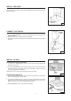
INSTALL THE DUCTWORK (DUCTED HOODS ONLY) ! ROOF CAP ROUND DUCT CAUTION: To reduce the risk of fire, use only metal ductwork. 1. Decide where the ductwork will run between the hood and the outside. 2. A straight, short duct run will allow the hood to perform most efficiently. 3. Long duct runs, elbows, and transitions will reduce the performance of the hood. Use as few of them as possible. Larger ducting may be required for best performance with longer duct runs. 4. Install a roof or wall cap.
PREPARE THE HOOD NON-DUCTED RECIRCULATION PLENUM (NON-DUCTED HOODS ONLY) Purchase a Non-ducted recirculation KIT from your dealer (Model DFKTPC50EC). 1. Insert the non-ducted recirculation plenum through the support frame openings. Fig. 8. 2. Through the support frame openings fit the duct connector to the plenum locking it with a turning movement. Fig. 9. 3. Fix a 5” duct to the duct connector of the non-ducted recirculation plenum. Fig.9. 4. Mount the 6”/5” adapter above hood. Fig. 10.
INSTALL THE HOOD SERRATED WASHERS Fix the hood to the support frame with (6) 3.9x9.5mm mounting screws and (2) serrated washers. MOUNTING SCREWS (3.9x9.5mm) FIG.13 CONNECT DUCTWORK (DUCTED HOODS ONLY) RETAINING SCREW 1. Use 6" round metal duct to connect the discharge collar on the hood to the ductwork above. 2. Use duct tape to make all joints secure and air tight. 3. Remove the temporary retaining screw from the lower flue and set it in place on the hood. 6” ROUND METAL DUCT FIG.
WIRING Note: Electrical wiring must be done by a qualified person(s) in accordance with all applicable codes and standards. This range hood must be properly grounded. Turn off electrical power at service entrance before wiring. 1. Remove the (2) screws of the upper flue and move the upper flue towards the bottom. 2. Feed 6” of power cable through the top opening of the support frame bracket (installed on ceiling) and into the wiring box. For the Non-Ducted Hoods, do not use the upper hole of the wiring box.
Major Appliance Warranty Information Your appliance is covered by a one year limited warranty. For one year from your original date of purchase, Electrolux will pay all costs for repairing or replacing any parts of this appliance that prove to be defective in materials or workmanship when such appliance is installed, used and maintained in accordance with the provided instructions. Exclusions This warranty does not cover the following: 1.
LISEZ ET CONSERVEZ CES INSTRUCTIONS ! SEULEMENT POUR UTILISATION DOMESTIQUE ! AVERTISSEMENTS POUR REDUIRE LES RISQUES D’INCENDIE, DE DECHARGES ELECTRIQUES OU DE DOMMAGES AUX PERSONNES, OBSERVEZ LES INSTRUCTIONS SUIVANTES: 1. N’utilisez cet appareil que comme cela est indiqué par le constructeur. Si vous avez des problèmes, contactez le fabriquant à l’adresse ou au numéro de téléphone indiqués dans la garantie. 2.
FONCTIONNEMENT Commandes Votre hotte fonctionne grâce à (4) boutons sur lesquels vous devez appuyer et qui se trouvent à la hauteur de vos yeux, sur le bord antérieur de votre hotte. Le bouton de la lumière allume et éteint les ampoules halogènes. Le bouton du ventilateur ON-bas/OFF fait fonctionner le ventilateur à la vitesse la plus basse. Le ventilateur doit être mis en fonctionnement grâce à ce bouton. Arrêtez le ventilateur en appuyant une deuxième fois sur ce bouton.
PREPAREZ LA HOTTE Enlever la hotte dans l’emballage et controller le contenu. Vous devez recevoir : 1 - Hotte 1 - Conduit décoratif 1 - Structure de support 1 - Sachet avec: 1 - Etrier de la structure de support 1 - Collier d’évacuation 4 - Vis d’assemblage (6 x 70) 13 - Vis d’assemblage (3,9 x 9,5mm Tête ronde) 2 - Vis d’assemblage (2.9 x 9.5mm Tête ronde) 4 - Rondelles D.6.
INSTALLATION DU SYSTEME D’EVACUATION (HOTTES CARÉNÉES) COUVERCLE DU TOIT TUYAU ROND ! ATTENTION: Pour réduire les risques d’incendie, n’utilisez que des tuyaux en métal. 1. Décidez où le tuyau rond doit être installé, entre votre hotte et l’extérieur. 2. Un tuyau droit et court permettra à votre hotte de fonctionner d’une façon plus efficace. 3. Un tuyau long avec des coudes et des transitions réduira le bon fonctionnement de votre hotte. En utiliser le moins possible.
PREPAREZ LA HOTTE DEFLECTEUR (HOTTES NON-CARENEES) Procurez-vous un KIT version recyclant l’air (Modele DFKTPC50EC) chez votre fournisseur. 1. Enfiler le déflecteur d’air dans la structure de support. Fig. 8. 2. Par les ouvertures de la structure de support, montez la bride sur le déflecteur en le bloquant avec un mouvement rotatoire. Fig. 9. 3. Fixer un tuyau de 5” (125mm) à la bride du déflecteur. Fig. 9. 4. Mounter l’adaptateur de 6”/5” sur la hotte. Fig. 10.
INSTALLATION DE LA HOTTE RONDELLES DENTEES Fixez la hotte à la structure de support au moyen des (6) vis d’assemblage 3.9x9.5mm et de (2) rondelles déntées. VIS D’ASSEMBLAGE (3.9x9.5mm) CONNEXION DU SYSTEME D’EVACUATION FIG.13 VIS D’ASSEMBLAGE PROVISOIRE (CONFIGURATIONS CARÉNÉES) 1. Reliez le collier d’évacuation qui se trouve sur votre hotte au système d’évacuation qui se trouve au-dessus au moyen d’un tuyau rond en métal de 6” (15cm). 2.
INSTALLATION ELECTRIQUE Remarque : le câblage électrique doit être effectué par une personne qualifiée, et conformément aux codes et normes en vigueur. La hotte doit être correctement reliée à la terre. Mettez l’alimentation électrique hors tension avant de procéder au câblage. 1. Retirez les (2) vis du conduit superieur etpositionné-le en bas. 2.
Informations sur la garantie des gros électroménagers Votre appareil est couvert par une garantie limitée d’un an. Pendant un an à partir de la date d’achat originale, Electrolux assumera les coûts des réparations ou du remplacement des pièces de cet appareil qui présente un défaut de fabrication ou de matériau, si cet appareil est installé, utilisé et entretenu selon les instructions fournies avec celui-ci. Exclusions Cette garantie ne couvre pas ce qui suit : 1.
SERVICE PARTS - LISTE PIECES DE RECHANGE MODEL PL36PC50EC KEY No. 1 9 12 14 26 45 48 49 53 62 63 64 67 86 92 113 115 116 118 119 124 125 165 223 228 229 230 234 240 250 332 407 998 ALA AQI DESCRIPTION (ENGLISH ) N.
SERVICE PARTS - LISTE PIECES DE RECHANGE MODEL PL36PC50EC - 19 -
04307544