Operating instructions HEAVY DUTY ANALYTICAL SIEVE SHAKER ANALYSETTE 18 Valid starting with: 18.
Fritsch GmbH Milling and Sizing Industriestraße 8 D - 55743 Idar-Oberstein Telephone: +49 (0)6784/ 70-0 Fax: +49 (0)6784/ 70-11 email: info@fritsch.de Internet: www.fritsch.
Certifications and CE conformity Certifications and CE conformity Certification Fritsch GmbH has been certified by the TÜV-Zertifizierungsgemeinschaft e.V. An audit certified that Fritsch GmbH conforms to the requirements of the DIN EN ISO 9001:2008. CE Conformity The enclosed Conformity Declaration lists the guidelines the FRITSCH instrument conforms to, to be able to bear the CE mark.
Table of contents Table of contents 1 Basic structure............................................................................... 6 2 Safety information and use........................................................... 8 2.1 Requirements for the user..................................................... 8 2.2 Scope of application............................................................... 8 2.2.1 Operating principle............................................................. 9 2.
Table of contents 5.5.8 Load.................................................................................. 27 5.5.9 Deleting............................................................................. 28 5.6 PC connection...................................................................... 28 6 Cleaning........................................................................................ 29 6.1 Sieves................................................................................... 29 6.2 Device.
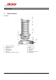
Basic structure 1 Basic structure Dry sieving 1 2 3 4 5 6 7 Clamping nut with grips Transparent screen Machine lid Rubber bumper Test sieve stack Guide rod Oscillating solenoid with armature 8 9 10 11 12 13 14 -6- Rubber profile Base Rubber bumper Flat spring Base plate Separate control device Rubber rings
Basic structure Wet sieving 1 2 3 4 5 6 7 8 Clamping nut with grips Transparent screen Machine lid Rubber bumper Test sieve stack Guide rod Oscillating solenoid with armature Rubber profile 9 10 11 12 13 14 15 16 -7- Base Rubber bumper Flat spring Base plate Separate control device Rubber rings Wide spreading spray diffuser with water hose Sieve pan with outlet
Safety information and use 2 Safety information and use 2.1 Requirements for the user This operating manual is intended for persons assigned with operating and monitoring the Fritsch ANALYSETTE 18. The operating manual and especially its safety instructions are to be observed by all persons working on or with this device. In addition, the applicable rules and regulations for accident prevention at the installation site are to be observed.
Safety information and use 2.2.1 Operating principle The ANALYSETTE 18 uses a three-dimensional sieving action for test sieves up to 450 mm in diameter. It has a self-adjusting amplitude. The whole system is driven by an electromagnetic drive. The device features a digital controller. Ten sieving parameter sets can be stored. As standard, it is delivered with a separate control device, which is equipped with a waterproof plug connection. 2.
Safety information and use DANGER! This symbol and keyword combination points out a directly hazardous situation that can result in death or serious injury if not avoided. WARNING! This symbol and keyword combination points out a possibly hazardous situation that can result in death or serious injury if not avoided. CAUTION! This symbol and keyword combination points out a possibly hazardous situation that can result in slight or minor injury if not avoided.
Safety information and use DANGER! This symbol and keyword combination designates contents and instructions for proper use of the machine in explosive areas or with explosive substances. Ignoring information with this designation will result in serious or fatal injury. DANGER! This symbol and keyword combination designates contents and instructions for proper use of the machine with combustible substances. Ignoring information with this designation will result in serious or fatal injury.
Safety information and use Tips and recommendations This symbol emphasises useful tips and recommendations as wells as information for efficient operation without mal‐ function. Further designations To emphasise procedure instructions, results, lists, references and other elements, the following designations are used in this manual: Designation Explanation Step-by-step procedure instructions 1., 2., 3. ...
Safety information and use WARNING! The maximum accepted concentration (MAC) levels of the relevant safety guidelines must be observed; if necessary, ventilation must be provided or the machine must be operated under an extractor hood. DANGER! Explosion hazard! – When sieving oxidizable substances, e.g. metals or coal, there is a risk of spontaneous combustion (dust explosion) if the share of fine particles exceeds a certain percentage.
Technical data 3 Technical data 3.1 Dimensions 585 x 575 x 1300 mm (depth x width x height) 3.2 Weight Device without test sieves: 135 kg Maximum weight of the sieve stack: 42 kg 3.3 Operating noise The sound emitted by the machine in the workplace was assessed using comparative noise measurement in accordance with DIN 45635-01 KI1. The A-rated equivalent continuous sound pressure level is: LpAeq = 73 (dB). 3.4 Voltage 230 volts 110 volts with a transformer 3.5 Frequency 50 hertz 60 hertz 3.
Installation 4 Installation 4.1 Transport The device is packaged in accordance with HPE packaging guidelines, which are defined by the Bundesverband Holzmittel, Paletten, Exportverpackungen e.V. (German Federation for Wood Packaging, Pallets and Export Packaging) and the Verein Deutscher Maschinenbauanstalten (Association of German Engineering Companies). The device is delivered on a transport pallet with a wooden cover. We recommend using a forklift or pallet truck for transporting the packed device.
Installation 4.2.
Installation Separate control device with connection cable, euro-plug and wall bracket A 3 m PVC water hose is included in the scope of delivery for the wet version 2 ring bolts 4.3 Setting up DANGER! Do not step under the transport pallet during transport. CAUTION! Use a transport crane to lift the device out of the packaging.
Installation 1. Screw the ring bolts provided in the corresponding bore holes. 2. Then lift the device out of the transport crate with the crane. 3. Place the device indoors, ideally, on a concrete floor. It does not have to be fastened to the surface. NOTICE! Do not use any rubber pads! NOTICE! Never operate the device while it is standing on the transport pallet! 4.4 Mounting the guide rods The sieve shaker is delivered fully assembled, apart from the guide rods. 1. Remove the ring bolts. 2.
Installation 3. Select an appropriate position for the wall bracket of the separate control device provided, and secure the bracket in place. 4. Connect the controller provided for the sieve shaker to the device drive. 4.5 Ambient conditions WARNING! Mains voltage! – The device may only be operated indoors. – The surrounding air may not carry any electrically conductive dust. – Maximum relative humidity 80% for temperatures up to 31°C, linearly decreasing down to 50% relative humidity at 40°C.
Installation CAUTION! Ignoring the values on the type plate may result in damage to the electrical and mechanical components. Before establishing the connection, compare the voltage and current values stated on the type plate with the values of the mains system to be used. 1. Plug the supplied power cord into the port (11) at the back of the device. 2.
Using the device 5 Using the device WARNING! If the sieves and clamping devices used are not genuine accessories, we assume no guarantee and exclude all liability for damage to the device or for personal injury. WARNING! Make sure before starting the machine that the sieves have been clamped correctly and that there are no loose parts on the device.
Using the device 5.1.2 Clamping 1. Set up the test sieve stack (3). 2. Pour the sieving stock in the top test sieve. 3. Put on the machine lid (2). 4. Tighten both nuts (1) at the same time. See Ä Chapter "Sieve analysis in accordance with ISO 2591‐1". 5.1.3 Preparing for wet sieving 1. Attach the wide spreading spray diffuser: Push the wide spreading spray diffuser (5) through the transparent screen (6); attach the sealing ring (7) and hose fitting (8). Tighten them. 2.
Using the device n DIN 66 165, part 1 basics - 1987 version n DIN 66 165, part 2 procedure - 1987 version The standard sheets can be purchased from Beuth-Verlag, Berlin. 5.3 The maximum particle size permitted for test sieves To avoid damaging the sieve base, the particle dimensions in a batch should not exceed 10 w0.7 (w is mesh width in mm). Example Nominal mesh width, w Maximum particle size mm approx. mm 0.045 1 0.25 4 1.00 10 4.00 25 5.
Using the device Bulk volume for test sieves with a diameter of 300 mm Nominal mesh width w Feeding volume Maximum sieve residue µm approx. cm3 approx. cm3 500 150 75 710 180 90 Bulk volume for test sieves with a diameter of 300 mm Nominal mesh width w Feeding volume Maximum sieve residue mm approx. cm3 approx. cm3 1.0 210 105 1.4 240 120 2.0 300 150 2.8 360 180 4.0 525 263 5.6 600 300 8.0 750 375 11.2 1200 600 16.0 1500 750 22.
Using the device Bulk volume for test sieves with a diameter of 400 mm Nominal mesh width w Feeding volume Maximum sieve residue µm approx. cm3 approx. cm3 125 100 50 180 120 60 250 140 70 355 160 80 500 200 100 710 240 120 Bulk volume for test sieves with a diameter of 400 mm Nominal mesh width w Feeding volume Maximum sieve residue mm approx. cm3 approx. cm3 1.0 280 140 1.4 320 160 2.0 400 200 2.8 480 240 4.0 700 350 5.6 800 400 8.0 1000 500 11.
Using the device 5.5 Start-up and operation a b Set points Actual values c d Adjustment buttons: left (-), right (+) Function buttons For setting the sieving time, interval time, and amplitude, there is a pair of buttons for each setting. The left button decreases the set point and the right button increases it. Hold one of the buttons down to scroll through the numbers more quickly. 5.5.
Using the device 5.5.3 Interval The interval time is set in seconds in the set point / actual time display. Display 00 = continuous operation without interruption. Display 01 - 99 = sieving time in seconds, interruption 1 second. After pressing "Start", the display switches to the actual value display, which shows the remaining interval time. 5.5.4 Amplitude The amplitude set point can be set in steps of 0.1 mm up to 2.0 mm.
Using the device 5.5.9 Deleting Switch the machine off and on again. The display shows 00. Press the "Store" button. Select the memory location to be deleted with the time +/- buttons and press "Store". 5.6 PC connection e Serial interface on the underside of the external control device The heavy duty analytical sieve shaker can be connected to a PC for exchanging data. This takes place via the serial interface using a RS 232 cable which is not included in the scope of delivery.
Cleaning 6 Cleaning DANGER! Mains voltage! – Before beginning with cleaning work, disconnect the mains plug and protect the device against being unintentionally switched back on! – Do not allow any liquids to flow into the device. – Indicate cleaning work with warning signs. – Put safety equipment back into operation after cleaning work.
Maintenance 7 Maintenance DANGER! Mains voltage – Before beginning with maintenance work, unplug the mains plug and protect the device against being unintentionally switched back on again! – Indicate maintenance work with warning signs. – Maintenance work may only be performed by specialised personnel. – Put safety equipment back into operation after maintenance or repair work.
Maintenance If a machine part and the corresponding equipment is replaced or changed, this part has to be checked again in accordance with EN 60 204‐1. We recommend that you con‐ tact our service team in the event of a fault or malfunction: Fritsch GmbH Milling and Sizing Industriestraße 8 D ‐ 55743 Idar‐Oberstein Phone: +49 (0)6784/ 70‐0 Fax: +49 (0)6784/ 70‐11 E‐Mail: info@fritsch.de Internet: http://www.fritsch.
Disposal 8 Disposal It is hereby confirmed that FRITSCH has implemented the directive 2002/95/EC of the European Parliament and Council from 27th January 2003 for the limitation of the use of certain dangerous substances in electrical and electronic devices.
Guarantee terms 9 Guarantee terms Guarantee period As manufacturer, FRITSCH GmbH provides – above and beyond any guarantee claims against the seller – a guaranty valid for the duration of two years from the date of issue of the guarantee certificate supplied with the device. Within this guarantee period, we shall remedy all deficiencies due to material or manufacturing defects free of charge. Rectification may take the form of either repair or replacement of the device, at our sole discretion.
Guarantee terms Costs not covered by the guarantee This guarantee excludes any costs for transport, packaging or travel that accrue in the event the product must be sent to us or in the event that one of our specialist technicians is required to come to your site. Any servicing done by persons not authorised by us and any use of parts that are not original FRITSCH accessories and spare parts will void the guarantee.
Exclusion of liability 10 Exclusion of liability Before using the product, be sure to have read and understood this operating manual. The use of the product requires technical knowledge; only commercial use is permitted. The product may be used exclusively within the scope of applications set down in this operating manual and within the framework of guidelines put forth in this operating manual and must be subject to regular maintenance.
Exclusion of liability Fritsch GmbH excludes any liability, warranty, or other obligation to compensate for damages, regardless of whether this liability, warranty, or other obligation is explicit or implicit, contractual or arising from unlawful acts or prescribed contractually, by law, or otherwise.
Safety logbook 11 Date Safety logbook Maintenance / Repair Name - 37 - Signature
Index 12 Index A Operation . . . . . . . . . . . . . . . . . . . . . . . . . . . . . . 26 Accident prevention . . . . . . . . . . . . . . . . . . . . . . . . 8 Amplitude . . . . . . . . . . . . . . . . . . . . . . . . . . . . . . 27 Authorised persons . . . . . . . . . . . . . . . . . . . . . . . . 8 P permitted particle size . . . . . . . . . . . . . . . . . . . . . 23 Power rating . . . . . . . . . . . . . . . . . . . . . . . . . . . . 14 Preparing for wet sieving . . . . . . . . . . . . . . . . . .
© 2014 Fritsch GmbH Milling and Sizing Industriestraße 8 D - 55743 Idar-Oberstein Telephone: +49 (0)6784/ 70-0 Fax: +49 (0)6784/ 70-11 email: info@fritsch.de Internet: www.fritsch.