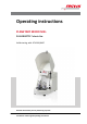
Operating instructions PLANETARY MICRO MILL PULVERISETTE 7 classic line Valid starting with: 07.
Fritsch GmbH Milling and Sizing Industriestraße 8 D - 55743 Idar-Oberstein Telephone: +49 (0)6784/ 70-0 Fax: +49 (0)6784/ 70-11 email: info@fritsch.de Internet: www.fritsch.
Certifications and CE conformity Certifications and CE conformity Certification Fritsch GmbH has been certified by the TÜV-Zertifizierungsgemeinschaft e.V. An audit certified that Fritsch GmbH conforms to the requirements of the DIN EN ISO 9001:2008. CE Conformity The enclosed Conformity Declaration lists the guidelines the FRITSCH instrument conforms to, to be able to bear the CE mark.
Table of contents Table of contents 1 Basic structure............................................................................... 6 2 Safety information and use........................................................... 7 2.1 Requirements for the user..................................................... 7 2.2 Scope of application............................................................... 7 2.2.1 Operating principle............................................................. 8 2.2.
Table of contents 6 Using the device........................................................................... 6.1 Choice of grinding bowls and grinding balls........................ 6.1.1 Size of the grinding balls................................................... 6.1.2 Number of balls per grinding bowl (independent of the material quantity)............................................................. 6.1.3 Calculated weight of a ball................................................ 6.
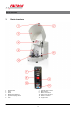
Basic structure 1 1 2 3 4 5 6 Basic structure Hood handle Latch Hood Membrane keyboard Spindle clamping device Lock 7 8 9 10 11 12 -6- Voltage rotary switch Main switch Mains connection Device fuse 2x 10 A T RS232 - interface Support disc
Safety information and use 2 Safety information and use 2.1 Requirements for the user This operating manual is intended for persons assigned with operating and monitoring the Fritsch PULVERISETTE 7 classic line. The operating manual and especially its safety instructions are to be observed by all persons working on or with this device. In addition, the applicable rules and regulations for accident prevention at the installation site are to be observed.
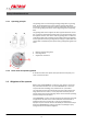
Safety information and use 2.2.1 Operating principle The grinding stock is crushed and ground by grinding balls in a grinding bowl. The centrifugal forces from the rotation of the grinding bowls around their own axis and from the rotating support disc act on the contents of the grinding bowl which consists of grinding stock and grinding balls.
Safety information and use By using the PULVERISETTE 7 classic line the customer agrees with this and recognizes that defects, malfunctions or errors cannot be completely excluded. To prevent risk of damage to persons or property or of other direct or indirect damage, resulting from this or other causes, the customer must implement sufficient and comprehensive safety measures for working with the PULVERISETTE 7 classic line.
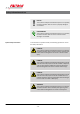
Safety information and use NOTICE! This symbol and keyword combination points out a possibly hazardous situation that can result in property damage if not avoided. ENVIRONMENT! This symbol and keyword combination points out a possibly hazardous situation that can result in environmental damage if not avoided.
Safety information and use WARNING! This symbol and keyword combination points out a directly hazardous situation due to hot surfaces. Ignoring information with this designation can result in serious burn injuries due to skin contact with hot surfaces. Safety information in the procedure instructions Safety information can refer to specific, individual procedure instructions.
Safety information and use Designation Explanation [Button] Operating elements (e.g. push button, switch), display elements (e.g. signal lamps) ‘Display’ Screen elements (e.g. buttons, function key assignment) 2.5 Device safety information Please observe! n Only use original accessories and original spare parts. Failure to observe this instruction can compromise the safety of the machine. n Accident-proof conduct is to be strictly followed during all work.
Safety information and use n Unauthorised alteration of the PULVERISETTE 7 classic line will void Fritsch's declaration of conformity to European directives and void the guarantee. n Only use the PULVERISETTE 7 classic line when it is in proper working order, as intended and in a safety- and hazard-conscious manner adhering to the operating manual. In particular, immediately rectify any malfunctions that could pose a safety hazard.
Safety information and use 2.6.2 1. Insert the included triangular key (A) into the bore hole on the bottom side of the PULVERISETTE 7 classic line and turn it to the right. 2. Unlock the latch (2) by turning it. 3. Pull the hood (3) up to open it. 4. The mill can only be switched on again if the hood (3) is closed and the safety lock (7) has been enabled again by turning the triangular key to the right. Imbalance switch The device switches off if there is excessive imbalance.
Safety information and use 1. Press and hold the STOP button on the control panel (4). 2. Switch on the device with the main switch (8) on the back of the device, and release the STOP button. 3. If POWER SUPPLY is flashing, the device is in setup mode. If POWER SUPPLY is not flashing, repeat the procedure. 4. NOTICE! In the display above the right "-" button (x) in the TIMER field, there must be a minus sign.
Safety information and use 5. To save and exit setup mode, press the STOP button. 2.7 Hazardous points CAUTION! – Crushing hazard when closing the hood (3). – Crushing hazard at the spindle clamping device (5). 2.8 Electrical safety 2.8.1 General information n The main switch (8) separates the device from the mains on two poles. n Switch off the main switch (8) if the planetary micro mill will be idle for an extended period of time (e.g. overnight). 2.8.
Safety information and use 2.8.4 Imbalance detection The device switches off if there is excessive imbalance.
Technical data 3 Technical data 3.1 Dimensions 500 x 370 x 530 mm (height x width x depth) 3.2 Weight Net: approx. 35 kg Gross: approx. 55 kg 3.3 Operating noise Emissions value of workplace according to DIN EN ISO 3746:2005 is up to 96dB (A). The value fluctuates strongly, depending on the speed, the grinding stock and the type of grinding bowl and grinding balls. 3.
Technical data 3.7 Electrical fuses Device fuse (10): 5 x 20 A T Micro-fuse 10 A T in the frequency converter 3.8 Material n Maximum feeding size 5 mm n Maximum feed amount 2 x 20 ml 3.
Installation 4 Installation 4.1 Transport The device is delivered on a transport pallet with a wooden cover. We recommend using a forklift or pallet truck for transporting the packed device. DANGER! Do not step under the transport pallet during transport. WARNING! Improper lifting can lead to personal injury or property damage. The machine is only to be lifted with suitable equipment and by qualified personnel. The guarantee excludes all claims for damage due to improper transport. 4.
Installation 4.3 Setting up DANGER! Do not step under the transport pallet during transport. CAUTION! The weight of the planetary micro mill is approx. 35 kg! CAUTION! Crushing hazard! Always lift with 2 persons. Hold the bottom edge of the housing when lifting the device. NOTICE! Operating the planetary micro mill while it is standing on the transport pallet is prohibited. n Lift the mill from the transport pallet with at least 2 persons. n Place the mill on a flat, stable surface.
Installation 4.4 Ambient conditions WARNING! Mains voltage! – The device may only be operated indoors. – The surrounding air may not carry any electrically conductive dust. – Maximum relative humidity 80% for temperatures up to 31°C, linearly decreasing down to 50% relative humidity at 40°C. n The room temperature has to stay between 5 - 40°C. n Altitudes up to 2000 m n Degree of pollution 2 according to IEC 664. 4.
Installation The mains voltage has been set at the factory to that of the specific country. The mains voltage only has to be adjusted if it deviates from the value on the type plate. If adjustment is necessary, proceed as in Ä Chapter 4.5.1.1 ‘Adjusting the mains voltage with the rotary switch (7)’ on page 23 and Ä Chapter 4.5.1.2 ‘Adjusting the mains voltage in setup mode’ on page 24. NOTICE! Fritsch mills are speed controlled. The devices are equipped for this with frequency converters.
Installation 4.5.1.2 1. The rotary switch (7) for adjusting the mains voltage is located on the back of the device. Rotate this switch to the required voltage. The slit in the rotary switch indicates the chosen voltage. 2. Connect the device to the mains. Adjusting the mains voltage in setup mode 1. Press and hold the STOP button on the front of the control panel. 2. Switch on the device with the main switch (8) on the back of the device, and release the STOP button. 3.
Installation 5. 4.5.2 To save and exit setup mode, press the STOP button. Setting device specification in setup mode NOTICE! "P7" must always be displayed in the REPETITIONS field. The Fritsch company assumes no guarantee for damage resulting from changing this setting.
Initial start-up 5 Initial start-up Perform initial start-up only after all work as described in Ä Chapter 4 ‘Installation’ on page 20 has been carried out. 5.1 Switching on n The device must be connected to the power supply if this has not been done already. n Switch on the device with the main switch (8) on the back of the device. n The POWER SUPPLY lamp lights up. 5.2 Function check CAUTION! Only perform the function check at a speed of 100 1/min.
Initial start-up 5.3 Switching off n Press the STOP button on the control panel. n Shortly after the mill comes to a standstill, the hood is unlocked and can be opened. n Switch off the device with the main switch (8) on the back of the device.
Using the device 6 Using the device CAUTION! Before starting the machine, make sure that the grinding bowl has been clamped correctly and that there are no loose parts inside the device. There is a risk of loose grinding bowls or parts being projected. Failure to observe this will render void the guarantee, and releases us from liability for any resulting damage to the device as well as for any resulting personal injury. NOTICE! During grinding, the temperatures in the grinding bowl may get very high.
Using the device CAUTION! The grinding element is subject to normal wear during use. Before every grinding operation, check the wall thickness of the grinding bowls. In the event of severe wear, replace the grinding bowl. If this is not done, the prevailing high centrifugal forces during grinding may cause the grinding balls to penetrate the bowl's wall and damage the mill.
Using the device Exception: Tungsten carbide balls (<20 mm) may be temporarily (a few minutes) combined with grinding bowls made of tempered steel. 6.1.1 Size of the grinding balls Type of feed material Suitable ball diameter Hard sample material with a maximum feed size of 2 - 5 mm 15 mm Fine material 0.5 mm 10 mm / 5 mm Homogenisation of dry or liquid samples 10 mm These are reference values: The size of bowls and grinding balls may need to be determined through experimentation.
Using the device Grinding bowl / 12 ml 45 ml Useful capacity (material to be ground) 0.5 - 5 ml 3 - 20 ml Stainless steel / 30 g 90 g 50 g 200 g Tempered steel Hardmetal tungsten carbide 6.1.3 Calculated weight of a ball Ball diameter in mm Material 5 10 15 Calculated weight of a ball in g Density in g/cm3 Agate 2.65 0.17 1.39 4.68 Silicon nitride 3.25 0.20 1.7 5.48 Sintered corundum 3.9 0.25 1.99 6.72 Zirconium oxide 5.7 0.37 2.98 10.07 Stainless steel 7.8 0.
Using the device NOTICE! If the filling quantity is lower than the specified minimum, this will result in increased wear due to abrasion! This can cause irreparable damage to the mill components. Grinding bowl Min. sample volumes Max. sample volumes 45 ml 3 ml 20 ml 12 ml 0.5 ml 5 ml 6.3 Filling the grinding bowl Do not fail to comply with the following sequence: 1. Place the grinding balls in the empty bowl. 2. Fill grinding stock onto the balls. 3.
Using the device 6.4.3 Reverse mode n Useful for mechanical alloying. n Improvement of the homogeneity of the sample during mixing. A low to medium speed is recommended for mixing (dry or wet). 6.4.4 Number and size of the balls Pre-grind course, hard material with large balls: Reduced percentage of fine material! Many small balls increase the percentage of fine material during extended running time. 6.4.
Using the device 6.4.7 Wet grinding (grinding in a suspension) DANGER! Explosion hazard! Ignition hazard! The device is not explosion-protected. If flammable liquids are used, make sure that the heat developing in the grinding bowl does not reach the solvent's boiling point. Program appropriate cooling phases. If the vapour pressure is too high, vapours may escape and ignite. If it can be avoided, we recommend using non-flammable liquids or liquids with a high boiling point.
Using the device 13 Spindle screw 14 Lock nut Clamping n Place the sealing ring and the lid onto the bowl. n Place the grinding bowl in the grinding bowl holder on the cork disc; do not force it! n Turn the spindle screw (13) all the way down until the pressure piece of the rubber disc lies flush on the lid. n Screw the spindle screw by hand until tight. n Turn the lock nut (14) all the way down until it lies flush on the clamping bracket. n Tighten the lock nut by hand.
Using the device CAUTION! The maximum permissible temperature of the grinding bowl outer casing is 100 - 110 °C (agate, max. 70 - 80 °C). The grinding duration is therefore based on the maximum bowl temperature. The grinding duration at which the temperature is not exceeded depends on the material, ball, and speed. For this reason, the user should determine it through experimentation.
Using the device 6.8 Setting the speed n Switch on the main switch (8) on the back of the device (I). n The green POWER SUPPLY ready status indicator lights up on the control panel. ROTATIONAL SPEED control panel area Press and hold the + or - button. The speed can be selected in steps of 10 between 100 and 800 1/min. The actual speed is displayed during operation. The nominal speed is briefly displayed when the + or - button is pressed. 6.
Using the device 6.9.1 Changing the time unit in setup mode 1. When the device has been switched off, press and hold the STOP button on the front control panel. 2. Switch on the device with the main switch (8) on the back of the device. 3. If POWER SUPPLY is flashing, the device is in setup mode. If POWER SUPPLY is not flashing, repeat the procedure. 4.
Using the device 6.11 Repetition of grinding / pause cycles REPETITIONS control panel area Press + or - button; select the number of repetitions (0..99). The number of remaining cycles is displayed during operation. 6.12 Conducting a grinding operation n After the conditions specified in Ä Chapter 6 ‘Using the device’ on page 28 have all been observed, close the hood (3). n Press the START button on the control panel. n The hood is locked and the mill starts up.
Using the device 6.12.2 Switching off n Press the STOP button on the control panel. n Shortly after the mill comes to a standstill, the hood is unlocked and can be opened. n Switch off the device with the main switch (8) on the back of the device. 6.13 Cooling the grinding bowl WARNING! Burn hazard! Grinding bowls can get very hot after long grinding durations. Wear protective gloves for removal after grinding or during the grinding breaks.
Cleaning 7 Cleaning DANGER! Mains voltage! – Before beginning with cleaning work, disconnect the mains plug and protect the device against being unintentionally switched back on! – Do not allow any liquids to flow into the device. – Indicate cleaning work with warning signs. – Put safety equipment back into operation after cleaning work. NOTICE! Cool grinding elements made of agate, sintered corundum, zirconium oxide and silicon nitride slowly and carefully.
Cleaning 7.2 Mill n After it has been switched off, the micro mill can be wiped down with a damp cloth.
Maintenance 8 Maintenance DANGER! Mains voltage – Before beginning with maintenance work, unplug the mains plug and protect the device against being unintentionally switched back on again! – Indicate maintenance work with warning signs. – Maintenance work may only be performed by specialised personnel. – Put safety equipment back into operation after maintenance or repair work. We recommend keeping a safety logbook Ä Chapter 13 ‘Safety logbook’ on page 52, where all work (maintenance, repairs......
Maintenance Functional part Task Test Maintenance interval V-belt Motor to planetary disc Check the voltage; remove the housing; the belt must not slacken by more than approx. 10 mm when pushed with your thumb.
Repairs 9 Repairs DANGER! Mains voltage! – Before beginning with repair work, unplug the mains plug and protect the device against being unintentionally switched back on. – Indicate repair work with warning signs. – Repair work may only be performed by specialised personnel. – Put safety equipment back into operation after maintenance work. 9.
Repairs Fault description Grinding stock escapes Runs unevenly with strong vibrations Cause Remedy Micro-fuse on the board blown To check the micro-fuse the housing has to be removed.
Disposal 10 Disposal It is hereby confirmed that FRITSCH has implemented the directive 2002/95/EC of the European Parliament and Council from 27th January 2003 for the limitation of the use of certain dangerous substances in electrical and electronic devices.
Guarantee terms 11 Guarantee terms Guarantee period As manufacturer, FRITSCH GmbH provides – above and beyond any guarantee claims against the seller – a guaranty valid for the duration of two years from the date of issue of the guarantee certificate supplied with the device. Within this guarantee period, we shall remedy all deficiencies due to material or manufacturing defects free of charge. Rectification may take the form of either repair or replacement of the device, at our sole discretion.
Guarantee terms Costs not covered by the guarantee This guarantee excludes any costs for transport, packaging or travel that accrue in the event the product must be sent to us or in the event that one of our specialist technicians is required to come to your site. Any servicing done by persons not authorised by us and any use of parts that are not original FRITSCH accessories and spare parts will void the guarantee.
Exclusion of liability 12 Exclusion of liability Before using the product, be sure to have read and understood this operating manual. The use of the product requires technical knowledge; only commercial use is permitted. The product may be used exclusively within the scope of applications set down in this operating manual and within the framework of guidelines put forth in this operating manual and must be subject to regular maintenance.
Exclusion of liability Fritsch GmbH excludes any liability, warranty, or other obligation to compensate for damages, regardless of whether this liability, warranty, or other obligation is explicit or implicit, contractual or arising from unlawful acts or prescribed contractually, by law, or otherwise.
Safety logbook 13 Date Safety logbook Maintenance / Repair Name - 52 - Signature
Safety logbook Date Maintenance / Repair Name - 53 - Signature
Index 14 Index A O Accident prevention . . . . . . . . . . . . . . . . . . . . . . . . 7 Adjusting to the mains voltage . . . . . . . . . . . . . . . 23 Ambient conditions . . . . . . . . . . . . . . . . . . . . . . . 22 Authorised persons . . . . . . . . . . . . . . . . . . . . . . . . 7 Opening the hood without mains connection . . . . . 13 Operating noise . . . . . . . . . . . . . . . . . . . . . . . . . . 18 Operating principle . . . . . . . . . . . . . . . . . . . . . . . . 8 Overload . . . . . .
© 2014 Fritsch GmbH Milling and Sizing Industriestraße 8 D - 55743 Idar-Oberstein Telephone: +49 (0)6784/ 70-0 Fax: +49 (0)6784/ 70-11 email: info@fritsch.de Internet: www.fritsch.