/ Perfect Charging / Perfect Welding / Solar Energy Fronius Symo 10 - 24 kW Installation 42,0410,2125 002-07102014
0
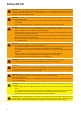
IMPORTANT SAFETY INSTRUCTIONS - SAVE THESE INSTRUCTIONS General These operating instructions contain important instructions for the inverter that must be followed during installation and maintenance of the inverter. The inverter is designed and tested according to international safety requirements, but as with all electrical and electronic equipment, certain precautions must be observed when installing and/or operating the inverter.
Safety EN-US WARNING! Incorrect operation and work performed incorrectly can cause serious injury and damage to property. Only qualified staff are authorized to commission your inverter and only within the scope of the respective technical regulations. Do not start operation or carry out maintenance work until you have read the "Safety Instructions" chapter. WARNING! An electric shock can be fatal. Danger from grid voltage and DC voltage from solar modules that are exposed to light.
CAUTION! Overloading the inverter may damage it. Observe the maximum current carrying capacity of different power categories (see Table A). Only connect a maximum of 33 A to each DC terminal. Connect the DC+ and DC- cables to the correct DC+ and DC- terminals on the inverter. Observe the maximum DC input voltage. Table A Power category Current carrying capacity 10.0-3 208-240 / 12.0-3 208-240 / 10.0-3 480 / 12.5-3 480 25 A / 16,5 A 15.0-3 480 / 17.5-3 480 / 20.0-3 480 / 22.7-3 480 / 24.
CONSERVER LES CONSIGNES DE SÉCURITÉ IMPORTANTES DES PRÉSENTES INSTRUCTIONS DE SERVICE Généralités Les présentes Instructions de service contiennent des indications importantes relatives au l'onduleur, qui doivent être respectées lors de l'installation et de l'entretien de l'onduleur. L'onduleur a été construit et contrôlé en tenant compte des directives de sécurité internationales.
Sécurité FR AVERTISSEMENT ! Les erreurs de commande et les erreurs en cours d'opération peuvent entraîner des dommages corporels et matériels graves. La mise en service de l'onduleur ne peut être effectuée que par du personnel formé à cet effet et dans le cadre des directives techniques. Avant la mise en service et l'exécution de travaux d'entretien, lire impérativement les consignes de sécurité. AVERTISSEMENT ! Une décharge électrique peut être mortelle.
ATTENTION ! Risque de dommages sur l'onduleur en raison d'une surcharge. Respecter la capacité de charge maximale des différentes classes de puissance (voir tableau A). Raccorder au maximum 33 A à une même borne de raccordement DC. Raccorder les câbles DC+ et DC- aux bornes de raccordement DC+ et DC- de l'onduleur en respectant la polarité. Respecter la tension d'entrée DC maximale. Tableau A Classe de puissance Capacité de charge 10.0-3 208-240 / 12.0-3 208-240 / 10.0-3 480 / 12.
INFORMACIÓN DE SEGURIDAD IMPORTANTE CONSERVE ESTE MANUAL DE INSTRUCCIONES Generalidades Este manual de instrucciones incluye instrucciones importantes para el inversor que deben cumplirse en relación con la instalación y el mantenimiento del inversor. El inversor ha sido diseñado y comprobado según las disposiciones de seguridad internacionales.
Seguridad ES ¡ADVERTENCIA! El manejo incorrecto y los trabajos realizados de forma defectuosa pueden causar graves daños personales y materiales. La puesta en servicio del inversor solo debe ser efectuada por personal formado y en el marco de las disposiciones técnicas. Antes de la puesta en servicio y la realización de trabajos de mantenimiento, resulta imprescindible leer las normas de seguridad. ¡ADVERTENCIA! Las descargas eléctricas pueden ser mortales.
¡PRECAUCIÓN! Riesgo de dañar el inversor por sobrecarga. Tener en cuenta la máxima intensidad de corriente admisible de los diferentes rangos de potencia (ver la tabla A). Conectar como máximo 33 A a un solo borne de conexión CC. Conectar los cables CC+ y CC- con la polaridad correcta a los bornes de conexión CC+ y CC- del inversor. Tener en cuenta la máxima tiempo máximo. Tabla A Clase de rendimiento Intensidad de corriente admisible 10.0-3 208-240 / 12.0-3 208-240 / 10.0-3 480 / 12.
Fronius Symo Installation Help English Français English www.fronius.com/QR-link/4204260202EA Français www.fronius.com/QR-link/4204260202FR Español www.fronius.
Fronius Symo Installation NEMA4X 10.0-3 - 12.0-3 208-240 ft. (m) > 11154 ft. > 3400 m 0 - 11154 ft. (0 - 3400 m) UDC max 600 V 10.0-3 - 24.0-3 480 UDC max ft. (m) > 9842 - 11154 ft. (> 3000 - 3400 m) > 8202 - 9842 ft. (> 2500 - 3000 m) > 6561 - 8202 ft. (> 2000 - 2500 m) 0 - 6561 ft.
8 in. 200 mm 8 in. 200 mm 4 in.
1 1 2 1 ON OFF Lock 1 1 3 4 lb 4.3 in.
1 1 NO NEMA ENCLOSURE TYPE 1 1 2 3 Al / St 0.2 - 0.3 in.
EN-US: mast, pole, pile, ... FR: mât, pile, barre, ...
Knockouts 1/2 in. ... DATCOM 3/4 in. - 1 1/4 in. ... AC ~ / DC = * * * * * * 1 1/4 in. (31,75 mm) METAL KNOCKOUTS Remove knockout-parts fallen into the connection area before hanging the inverter to the wall bracket! ** ** * Conduit size 1/2 in. (12,7 mm) / 3/4 in. (19,05 mm) / 1 in. (25,4 mm) ** Conduit size 1/2 in. (12,7 mm) / 3/4 in. (19,05 mm) / 1 in. (25,4 mm) / 1 1/4 in. (31,75 mm) 1 in. 1 1/4 in. 1 in.
* 1 2 * 17
Appropriate Grids Delta No neutral conductor Setup: 208 240 220 BR 50HZ Nominal voltage: 208 V 240 V 220 V 220 V 208 - 240 V L1 = ~ L3 L2-L3 L2 120° WYE Neutral conductor available Setup: 208N 220N BR N 50HN Nominal voltage: 208 V 220 V 220 V 208 - 240 V 480N 440N 50HN 480 V 440N 50 HN Stinger Neutral conductor available Setup: 240N Nominal voltage: 240 V L1 = N ~ L3 L2-L3 L2 120° L1 = ~ L3 L3-N L2-N N 120° 18 L2
Connection Diagram & Connection Area DC = (+) Fronius Symo DC = terminal block L3 L2 L1 N DC = disconnect Grounding terminal DC = (-) PV frame ground Grounding electrode terminal * N L1 L2 L3 Energymeter AC ~ distribution panel Lockable AC ~ disconnect switch Main grounding system DC = Disconne Cu / Al ct Cu max. Class 4 Cu: min. AWG 14 - max. AWG 6 Al : AWG 6 15.93 lb-in / 1.33 ft. lb. / 1.8 Nm DC = (+) DC = (-) AC ~ All terminals are suitable for multi conductor applications.
10AWG and 10 AWG Copper (CU) - stranded and stranded Copper (CU) - stranded and solid 10AWG and 12 AWG Copper (CU) - stranded and stranded Copper (CU) - solid and solid 10AWG and 14 AWG Copper (CU) - stranded and stranded Copper (CU) - solid and solid 12AWG and 12 AWG Copper (CU) - stranded and stranded Copper (CU) - solid and solid 12AWG and 14 AWG Copper (CU) - stranded and stranded Copper (CU) - solid and solid 14AWG and 14AWG Copper (CU) - stranded and stranded Copper (CU) - solid and solid
AC ~ AC~ Minimum AWG in acc. to NEC Copper (Cu) / Aluminium (Al) Copper (Cu) / Aluminium (Al) Copper (Cu) / Aluminium (Al) 10.0-3 208-240 12.0-3 208-240 208 VAC AWG 10 / AWG 10 AWG 10 / AWG 8 220 VAC AWG 10 / AWG 10 AWG 10 / AWG 8 240 VAC AWG 12 / AWG 10 AWG 10 / AWG 10 10.0-3 480 12.5-3 480 15.0-3 480 440 VAC AWG 14 / AWG 12 AWG 14 / AWG 12 AWG 14 / AWG 12 480 VAC AWG 14 / AWG 12 AWG 14 / AWG 12 AWG 14 / AWG 12 17.5-3 480 20.0-3 480 22.
1 1 2 1 1 GND GND OFF Cu / Al Cu max. Class 4 > 10 in. (> 250 mm) PE 0.6 in. (15 mm) AC ~ PE > 8 in. (> 200 mm) AC ~ max. 80 A IΔN ≥ 100 mA § ? National Standards 22 RCD YES Type A 15.93 lb-in 1.33 ft. lb. 1.
DC = 1 1 2 1 AWG 14 ... AWG 6 copper direct AWG 6 aluminum direct AWG 4 ... AWG 2 copper or aluminum with input combiner > AWG 10 (6 mm²) 0.59 in. (15 mm) DC = DC- 2 2 DC+ 2.76 in.
1 1 3 4 10.0-3 - 24.0-3 480 UDC max ft. (m) 10.0-3 - 12.0-3 208-240 DC = (-) UDC max 0 - 11154 ft. (0 - 3400 m) 600 V 850 V 900 V 950 V 1000 V DC = (+) 1 2 1 2 DC = ft. (m) > 9842 - 11154 ft. (> 3000 - 3400 m) > 8202 - 9842 ft. (> 2500 - 3000 m) > 6561 - 8202 ft. (> 2000 - 2500 m) 0 - 6561 ft.
Installing Datamanager 2.0 1 1 2 1 1 3 1 1 1 4 5 1 TX20 2 10.62 lb-in 0.89 ft. lb. 1.
DATCOM Connection 1 1 2 1 1 1 3 26 4
1 1 5 6 1 7 27
Operation 1 1 ON OFF Lock 17.7 lb-in / 1.48 ft. lb. / 2.0 Nm 4.3 in. 1 1 2 3 AC ON 2 1 ON OFF Lock 1 * Setups: 1 4 5 CONFIG Country inst. new EX 240N * V0.0.03 V0.0.
1 1 9 12 BASIC 1 13 MPP TRACKER 2 1 2 29
Lock 1 1 2 1 1 1 * * max 0.28 in. (7 mm) EN-US: The padlock is not part of the scope of delivery for the inverter. 1 3 FR: Le cadenas n'est pas compris dans la livraison de l'onduleur. ES: El candado no está parte del volumen de suministro del inversor. 1 * * 30 max 0.28 in.
Firmware Update EN-US: USB + IMPORTANT! Firmware may only be updated by Fronius service technicians or Fronius service provider.
Field Adjustable Trip Points Setup 208/208N Trip Limit 120V Setup 208/208N Trip Limit NL-Mon 120V UAC [V] Clearing Time [s] Clearing Time [cyl] UAC [V] Clearing Time [s] Clearing Time [cyl] U < 50% 60 0.16 9 60 0.16 9 50 ≤ U < 88 % 106 2 118 106 2 118 110 < U < 120 % 132 1 58 132 1 58 U ≥ 120 % 144 0.16 9 144 0.16 9 UImin adjustable UOmin adjustable 60 - 119 0.016 - 21.0 1 - 1260 60 - 119 0.016 - 21.0 1 - 1260 UImax adjustable UOmax adjustable 121 - 166 0.016 - 21.
Setup 440N Trip Limit 254V Setup 440N Trip Limit NL-Mon 254V UAC [V] Clearing Time [s] Clearing Time [cyl] UAC [V] Clearing Time [s] Clearing Time [cyl] U < 50% 127 0.16 9 127 0.16 9 50 ≤ U < 88 % 225 2 118 225 2 118 110 < U < 120 % 280 1 58 280 1 58 U ≥ 120 % 305 0.16 9 305 0.16 9 UImin adjustable UOmin adjustable 120 - 252 0.016 - 21.0 1 - 1260 120 - 252 0.016 - 21.0 1 - 1260 UImax adjustable UOmax adjustable 256 - 322 0.016 - 21.0 1 - 1260 256 - 322 0.016 - 21.
Setup 50HN Trip Limit 240V Setup 50HN Trip Limit NL-Mon 240N UAC [V] Clearing Time [s] Clearing Time [cyl] UAC [V] Clearing Time [s] Clearing Time [cyl] U < 50% 120 0.16 8 120 0.16 8 50 ≤ U < 88 % 211 2 100 211 2 100 110 < U < 120 % 264 1 50 264 1 50 U ≥ 120 % 288 0.16 8 288 0.16 8 UImin adjustable UOmin adjustable 120 - 252 0.020 - 21.0 1 - 1050 120 - 252 0.020 - 21.0 1 - 1050 UImax adjustable UOmax adjustable 251 - 322 0.020 - 21.0 1 - 1050 251 - 322 0.016 - 21.
UAC [s] [cyl] UImin UImax UOmin UOmax Unom FImin FImax FOmin FOmax AC Voltage Unit: Seconds Unit: Cycles (1) U Inner Limit min (min. inner limit voltage) U Inner Limit max (max. inner limit voltage) U Outer Limit min (min. outer limit voltage) U Outer Limit max (max. outer limit voltage) nominal Voltage F Inner Limit min (min. inner limit frequency) F Inner Limit max (max. inner limit frequency) F Outer Limit min (min. outer limit frequency) F Outer Limit max (max.
Fronius Worldwide - www.fronius.com/addresses Fronius International GmbH 4600 Wels, Froniusplatz 1, Austria E-Mail: pv-sales@fronius.com http://www.fronius.com Fronius USA LLC Solar Electronics Division 6797 Fronius Drive, Portage, IN 46368 E-Mail: pv-us@fronius.com http://www.fronius-usa.com Under http://www.fronius.