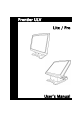
F ro n t ie r U L V L it e / Pro U s e r’s M a n u a l
Preface About this Manual Thank you for purchasing our Frontier Touch Terminal. This terminal offers highly enhanced features, with easy connection to various optional devices for optimal performance. This user manual describes how to setup and connect your terminal. Copyright © Copyright 2006 All rights reserved. This product and related documentation are protected by copyright and are distributed under licenses restricting their use, copying, and distribution.
Preface Operating Instructions • Keep this manual for future reference. • Keep this equipment from moisture and dust. • Place the equipment on a stable surface before setting it up. • If there is any of the following situation arise, notify a qualified service technician immediately: The power cord or plug is damaged. Liquid has been spilt on to the equipment. The equipment has been dropped and damaged. The equipment does not function normally.
Preface Federal Communications (FCC Statement) This device complies with FCC Rules Part 15. Operation is subject to the following two conditions: • This device may not cause harmful interference. • This device must accept any interference received including interference that may cause undesirable operation. This equipment has been tested and found to comply within the limit of a Class A digital device, pursuant to Part 15 of the FCC Rules.
Content Chapter 1 ..........................................................................................................1 Welcome ................................................................................................................. 1 Overview of Frontier ULV.............................................................................. 1 Rear View ................................................................................................... 2 OSD Control Buttons ........................
Chapter 1 Chapter 1 Welcome Congratulations on your purchase of this POS terminal. Your easy-to-use POS terminal is designed to help you enhance your business flexibility by offering a superior customer experience. Overview of Frontier ULV ULV Lite ULV Pro Counter space-saver Powerful expansion capability Dual display for advertising Model CPU Frontier ULV 1.0 Lite VIA Eden 1GHz (Fan-less) Chipset HDD Frontier ULV 1.5 ~ 2.0 Pro Lite Pro VIA C7 1.5 GHz ~ 2.0 GHz VIA CN700 + 8237R+ 2.5” x 1 2.
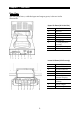
Chapter 1 — Welcome Rear View The rear panel view, with the input and output ports, is shown in the illustration.
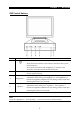
Chapter 1 — Welcome OSD Control Buttons ICON 1 2 Power LED 3 Brightness + 4 Brightness – 5 Speaker + 6 Speaker – FUNCTION Press the Power button to start up the system. Press the Power button for 4 seconds to shut down the system from hardware. Press the Power button and “Brightness +” button for 4-6 seconds to reset the system from the hardware. Red: Standby mode. Green: System start up.
Chapter 1 — Welcome Features This POS terminal comes equipped with the following features: Noise-free • The fan-less, noise free design of the Frontier ULV is ideal for noise-intolerant environment such as hospitals, museum, and SPA resorts, etc. Low power consumption • ULV (Ultra Low Voltage) design of the device is embedded with a unique chip set and CPU renders power saving function.
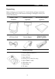
Chapter 1 — Welcome Unpacking Before setting up your Frontier ULV, check that the package contains the following items. If any of the items are missing or damaged, contact your vendor immediately. Frontier Touch Terminal Customer Display (optional) 2nd Customer Display (optional) AC Power Cord Power Adapter Magnetic Stripe Reader (optional) Accessory Package 1. Screws (black) for MSR x 1 2. Driver CD disc 3. User's Manual 4. DC24V power cable (Pro only) 5. PS/2 COMBO Y cable 6. USB rubber cove 7.
Chapter 2 Chapter 2 Getting Started This chapter describes how to install the optional accessories on your Frontier Touch Terminal for optimal serviceability. Pre-installation Notice Before you start installing your Frontier ULV, please read the following notices carefully. 1. The Frontier ULV does not support PCI slot. 2. Do not plug in or unplug any interior devices, such as memory module or any function card, when the ATX PSU is powered on. 3.
Chapter 2 — Getting Started Preset voltage setting for MSR 1. The MSR default setting is ISO Track 1 & 2. (For customized track settings, advise the manufacturer before production.) 2. In event of any requirement to change the setting of the MSR, run Setting utility in the driver CD provided in the accessory package. 3. The normal swiping card speed of the MSR is 10 to 100 cm/sec. (based on the ISO 7812 standard).
Chapter 2 — Getting Started Hardware Installation Installing the Adapter and Internet for Lite type To install the adapter and Internet cable for Lite type, do the following: 1. Connect the Internet RJ 45 cable and the power cable to the connectors and arrange the cables in the clamps as shown. RJ 45 connector 2. Power adapter connector Replace the extension base cover and affix it to the base with two M3 back screws.
Chapter 2 — Getting Started Installing the Adapter and Internet for Pro type To install the adapter and Internet cable for Pro type, do the following: 1. Take out the cable clamps from the accessory package and attach them to the position as shown. Connect the Internet RJ 45 cable and the power cable to the connectors and arrange the cables in the clamps. RJ 45 connector Power adapter connector Cable clamp 2.
Chapter 2 — Getting Started Installing the Customer Display for Lite type Follow the procedures below to install the Customer Display. 1. Connect the VFD DB 9 cable to the connector as shown. 2. Replace the base cover and affix it with two M3 screws. 3. Attach the Customer Display to the base of the Frontier ULV Terminal with two M3 screws. 4. Lock the Customer Display to the customer display pole bracket with two M3 screws.
Chapter 2 — Getting Started Installing the 2nd display (for Pro type only) To install the 2nd display onto the Frontier ULV Terminal, do the following: 1. Connect the DB 15 cable to the connector on the back of the Frontier ULV Terminal LCD screen and arrange the cable in the clamp as shown. DB 15 connector Cable clamp 2. Replace the base cover. Connect one end of the DC 12V adapter cable to the base and allow the other end of the cable pass through the hole on the 2nd Display cover stand.
Chapter 2 — Getting Started 4. Install the 2nd Display and lock it to the stand with four M3 screws. Installing the MSR To install the MSR onto the LCD display, do the following: 1. Attach the MSR device jack to the MSR socket on the side of the LCD display. 2. Affix the upper and lower MSR wires firmly to the slots on the side of the LCD. 3. Lock the MSR securely on the LCD display with two M3 screws. LCD Operating Angle The LCD display is equipped with an adjustable hinge of 0° to 90°.
Appendix Appendi x Technical Information Specifications ITEM SPECIFICATION Model Name Frontier ULV All in One Touch POS System Processor Supports VIA Eden CPU 1.0 GHz or C7 CPU up to 2.0GHz Memory 200-pin DDR RAM *1, up to 2GB (DDR333/400) System Core Chipset North Bridge: VIA CN-700 South Bridge: VIA 8237R+ BIOS Award BIOS with enhanced ACPI 1.0 PnP/APM/DMI/ESCD/PCI bus 2.
Appendix — Technical Information ITEM SPECIFICATION Thermal Solution One heat-sink (Fan-less) or heat-sink with Fan (Base on Fan Speed Control technology) for CPU and North Bridge Chip Compact Flash Card One bootable compact flash card socket (Type I/II) Cash Drawer Port One cash drawer port with status sensor. (EPSON ESC Pin define) System Power DC 24V/ 5A /120W external power adapter with internal DC to DC power inverter. AC Power Source AC 90 to 264V Full Range.
Appendix — Technical Information ITEM SPECIFICATION 32 Keys Programmable POS Keyboard Note: Specifications are subject to change without notice. Frequently Asked Questions (FAQ) Question 1: Why does the system appear unstable after updating BIOS? Answer: Load optimized defaults (or load SETUP Default) after flashing BIOS. If the system remains unstable, clear CMOS to solve the problem. Question 2: How do I clear CMOS? Answer: To clear CMOS, do the following: 1.