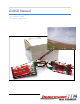
EzOSD Manual ‘Pro Features’ Guide Preliminary.
Contents Overview ....................................................................................................................................................... 3 Sensor Board PCB.......................................................................................................................................... 3 Blanking the OSD display .............................................................................................................................. 4 Rx RSSI Display ..
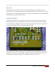
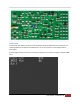
Overview This document contains details on some of the more advanced features of the EzOSD. These are features which are not required by any means to fly FPV with the EzOSD, but are certainly ‘nice to have’. The two features currently documented here are receiver signal strength display, and enabling/disabling the OSD display using a spare receiver channel. Sensor Board PCB The EzOSD current sensor contains a small microcontroller.
Blanking the OSD display The pads marked ‘PWM’ may be used to blank the OSD display during flight. Two connection possibilities exist: 1) Take a 3‐pin 0.1” header, trim the pins a little, and solder them into the three holes. 2) Take a standard 3‐wire servo cable, and solder the three wires to the three PWM pads. In both cases, the left‐most PWM pin is the PWM signal (orange, white, or yellow in the servo cable), and the right‐most is ground (black or brown in the servo cable).
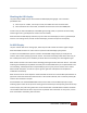
Calibration A new feature was added in firmware version 0.99 which allows the RSSI levels to be calibrated. This calibration MUST be completed if the RSSI feature is to be used, if not the values displayed will be meaningless. A second page is present in the menu, accessed by moving the cursor down the page, and past the Exit entry.
To calibrate the system, highlight the RSSI Max entry, and, with your R/C transmitter ON, press the menu button. The value to the right should change, but always remain at around a value of ~200. Next, reduce the length of your R/C transmitter antenna by sliding it down into the transmitter and move the RC plane with the receiver away from it, gradually increasing the distance between the two.