
User Manual

www.frsky-rc.com
18/05/12
1
Instruction Manual for FrSky D8R-XP
1. Introduction
1.1 Compatibility
Compatible with FrSky two way telemetry modules: DFT, DJT, DHT, DHT-U
1.2 Specifications
Dimension: 55*25*14mm
Weight: 12.4g
Operating Voltage Range: 3.5V-10.0V
Operating Current: 100mA
Operating Range: full range (>1.5km)
1.3 Features
1) Two external analog telemetry ports (A1&A2) and one digital data-stream port (Rx);
2) RSSI (PWM) and CPPM output - If CH3 and CH4 are connected by a jumper, CH1 will output CPPM for CH1~CH8,
and CH2 will output RSSI (PWM);
3) When side port pins of A1 and X are connected by the jumper, A1 will change from external analog telemetry
port to internal built-in battery voltage sensor;
4) Firmware upgradeable;
5) Two switchable PPM modes - FS mode and HS mode;
6) Alarm warning on low voltage, poor reception, etc.
2. Set up
2.1 Bind procedure
1) Ascertain that the transmitter is in the PPM mode. Turn off the transmitter.
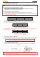
2) Turn on the transmitter while holding the F/S button on the transmitter module (Ensure that both switches on the
transmitter module are OFF when using D8R-XP in two way mode). Release the button. The RED LED on the transmitter module
will flash, indicating the transmitter is ready to bind to the receiver.
3) Connect battery to the receiver while holding the F/S button on the receiver. The RED LED on the receiver will flash,
indicating the binding process is completed. Turn off both the transmitter and the receiver.
4) Turn on the transmitter and connect the battery to the receiver. The GREEN LED on the receiver will indicate the
receiver is receiving commands from the transmitter. The receiver/transmitter module binding will not have to be repeated, unless
one of the two is replaced.
Warning: Battery or servos are NOT to be plugged into side ports (A1/A2/Rx), otherwise damage may occur.
2.2 Range check
A pre-flight range check should be done before each flying session. Reflections from nearby metal fences, concrete
buildings or trees can cause loss of signal both during range check and during the flight.
The following steps are to be followed to perform the range check of the model before the flight:
1) Place the model at least 60cm (two feet) above non-metal contaminated ground (e.g. on a wooden bench).
2) The receiver antennas should be separated in the model, and do not touch the ground.
3) Place the antenna of the transmitter in a vertical position.
4) Turn on the transmitter and the receiver, press the F/S button of the transmitter module for 4 seconds to enter range
check mode, the RED LED of the transmitter module will be off, GREEN LED will flash rapidly, and the beeper will sound. The
effective distance will be decreased to 1/30 of full range.
5) Walk away from the model while simultaneously operating the controls on the transmitter, confirming that all controls
operate normally to a distance of at least 30 meters (~30 yds).
6) Press the F/S button of the transmitter module for 1S-4S to exit range check mode, RED LED will be back on, indicating
normal operation is back.
2.3 Setting failsafe
Failsafe is a useful feature in which all controls move to a preset position whenever the control signal is lost for a period of
time. D8R-XP supports failsafe function for all channels.
Follow the steps below to set failsafe positions for each channel:
1) Bind the receiver first and turn on both the transmitter and the receiver;
2) Move the controls to the desired failsafe position for all channels;
3) Press briefly the F/S button on the receiver (less than 1 second). The transmitter module will make a long “beep”,