
User Manual

www.frsky-rc.com
Instruction Manual for DHT
1. Introduction
1.1 Description & compatibility
1-WAY Compatible with non-telemetry receivers:
V8R4/V8R7-HV/V8R7-SP/V8FR-HV
2-WAY Compatible with telemetry receivers:
D4FR/D6FR/D8R/D8R-II
FW Firmware Upgrade
1.2 Specifications
Dimension: 55*34*8mm (2.17”L x 1.34”W x 0.32”T)
Operating Voltage Range: 6.0V-13.0V
Operating Current: 50mA
Output Power: 60mW
Resolution: 3072 (>11bit)
2. Set Up
2.1 Installation process
1) Open the transmitter and find a clear position to locate the DHT module, the antenna connector, the small electronic
panel. The location of the antenna should be such that there is no metal touching the antenna after it is mounted.
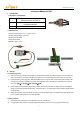
2) Locate the battery power supply line, GND and PPM signal line. These are often a three-wire bundle or ribbon cable
connected to a separate transmitter circuit card. Use a voltmeter and/or oscilloscope to help identify the function of
each wire. (REDÆV+; BLACKÆGND; YELLOWÆPPM)
3) Drill four holes on the transmitter as the picture guided, two holes on both sides are designed for screw installation,
others for green/red color LED and the button.(see picture above); then drill another hole for installing toggle switch in
a suitable place.
4) Attach the transmitter antenna to the RF connector. Turn the transmitter power on and check the power indicator LED
on the new DHT control panel. It is normally light RED.
2.2 Bind procedure
1) Ascertain that the transmitter is in the PPM mode. Turn the transmitter off.
2) Change toggle switch position to required mode to work with the receiver you are using. See the table above.
- 1 -