Electric Cooker Models 17EC, 17ECS, ESW and EWBS Installation, Operation, Service & Parts Manual Frymaster, a member of the Commercial Food Equipment Service Association, recommends using CFESA Certified Technicians.
NOTICE IF, DURING THE WARRANTY PERIOD, THE CUSTOMER USES A PART FOR THIS ENODIS EQUIPMENT OTHER THAN AN UNMODIFIED NEW OR RECYCLED PART PURCHASED DIRECTLY FROM FRYMASTER/DEAN, OR ANY OF ITS AUTHORIZED SERVICE CENTERS, AND/OR THE PART BEING USED IS MODIFIED FROM ITS ORIGINAL CONFIGURATION, THIS WARRANTY WILL BE VOID.
ELECTRIC COOKER MODELS 17EC, 17ECS, ESW AND EWBS TABLE OF CONTENTS CHAPTER 1: General Information 1.1 Parts Ordering and Service Information 1.2 Safety Information 1.3 Equipment Description 1.4 Installation, Operating, and Service Personnel 1.5 Definitions 1.6 Shipping Damage Claim Procedure 1-1 1-1 1-2 1-3 1-3 1-4 CHAPTER 2: Installation Instructions 2.1 General Installation Requirements 2.2 Caster/Leg Installation 2.3 Pre-Connection Preparations 2.
6.4.1 6.4.2 6.4.3 6.4.4 6.4.5 6.4.6 6.5 6.6 How the Power Supply System Works ........................................................................ 6-11 How the Computer Works............................................................................................ 6-11 How the Autofill/Autoskim System Works ................................................................. 6-12 How the Water Heating System Works .......................................................................
7.6 Control Components..................................................................................................... 7-24 Cookpot and Drain Components .................................................................................. 7-25 Electronics .................................................................................................................... 7-26 Water Supply System Components ..............................................................................
THIS PAGE INTENTIONALLY LEFT BLANK.
ELECTRIC COOKER MODELS 17EC, 17ECS, ESW AND EWBS CHAPTER 1: GENERAL INFORMATION 1.1 Parts Ordering and Service Information In order to assist you as quickly as possible, the Frymaster Factory Authorized Service Center (FASC) or Service Department representative requires certain information about your equipment. Most of this information is printed on a data plate affixed to the inside of the door. Parts orders may be placed directly with your local FASC or distributor.
WARNING boxes contain information about actions or conditions that may cause or result in damage to your equipment, and which may cause your equipment to malfunction. DANGER DANGER boxes contain information about actions or conditions that may cause or result in injury to personnel, and which may cause damage or malfunctioning of your equipment 1.
previous page) or a specially modified CM III computer. The equipment may be configured as single cooker (E1WBS) or as a battery of two cookers (E2WBS). “SD” following the model designation indicates a stainless steel cookpot and door, and an enameled cabinet. “SC” following the model designation indicates all stainless steel components. Optional features include automatic water filling and a manual skim feature.
What to do if your equipment arrives damaged: 1. File a claim for damages immediately, regardless of the extent of damages. 2. Inspect for and record all visible loss or damage and ensure that this information is noted on the freight bill or express receipt and is signed by the person making the delivery. 3. Concealed loss or damage that was unnoticed until the equipment was unpacked should be recorded and reported to the freight company or carrier immediately upon discovery.
ELECTRIC COOKER MODELS 17EC, 17ECS, ESW AND EWBS CHAPTER 2: INSTALLATION INSTRUCTIONS 2.1 General Installation Requirements PROPER INSTALLATION IS ESSENTIAL FOR EFFICIENT, TROUBLE-FREE OPERATION OF YOUR COOKER. ANY UNAUTHORIZED ALTERATIONS MADE TO THIS EQUIPMENT WILL VOID THE FRYMASTER WARRANTY. Upon arrival, inspect the cooker carefully for visible or concealed damage. (See Shipping Damage Claim Procedure in Chapter 1.
2.2 Caster/Leg Installation Depending upon the specific configuration ordered, your unit might have been shipped without installed casters or legs. If casters or legs are installed, you may skip this section and proceed to Section 2.3, Pre-Connection Preparations. If your unit requires the installation of casters/legs, install them in accordance with the instructions included in your accessory package. 2.
Whichever option is chosen, Teflon thread-seal tape, Loctite™ PST56765 or equivalent thread sealer must be used when installing the fittings. NOTE: Depending on specific model ordered, either hot or cold water, or both, may be connected to the unit. If available, connecting hot water will minimize the time required to bring the unit to a boil when filling with fresh water. NOTE: In order for the water level sensors to work properly, a certain amount of mineral content in necessary in the water.
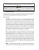
FIELD CONNECTION WIRING DIAGRAMS SINGLE PHASE FIELD CONNECTION L2 L1 L3 SINGLE PHASE (NO NEUTRAL) FIELD CONNECTION NEUTRAL TO L3 L2 L1 1HV L3 1HV 1C1 2HV 1 1C2 FROM TRANSFORMER 1C1 2HV 1 1C2 FROM TRANSFORMER 3HV 4 1C3 3 4 1C3 5 2 3HV 5 2 3 6 6 FROM TRANSFORMER FROM TRANSFORMER 3 PHASE 3 WIRE (DELTA) FIELD CONNECTION L2 L1 3 PHASE 4 WIRE (WYE) FIELD CONNECTION L3 L2 L1 L3 N FROM TRANSFORMER FROM TRANSFORMER FROM TRANSFORMER 1HV 2HV 3HV 1C1 1C2 1C3 5 4 1 2
ELECTRIC COOKER MODELS 17EC, 17ECS, ESW AND EWBS CHAPTER 3: OPERATING INSTRUCTIONS 3.1 Spaghetti Magic III Controller (As Used on 17EC and 17ECS Units) 1 2 1 2 3 4 5 3.1.1 3 4 Numeric Keypad Boil Mode Indicator Boil Mode Switch Power Switch LED Display 5 6 7 6 7 8 9 8 9 Skim Switch (w/Autoskim only) Timer Start Switch Simmer Mode Switch Simmer Mode Indicator Introduction CAUTION The Spaghetti Magic III (SMS III) computer used in 17EC/17ECS units is specially configured for them.
LOW WATER SENSING automatically de-energizes the heating element if the water in the cookpot drops too low. When the water level in the cookpot is below the sensor probes, such as when draining and cleaning the cookpot, the controller display will read LO. NORMAL WATER LEVEL SENSING, on units configured with the AutoFill feature, automatically adds water during or after a cooking cycle if the water level is low. With this automatic filling feature, the water level does not have to be continuously monitored.
When the water is at or above the minimum temperature for boiling (transition temperature), the controller pulses power to the elements at a programmable rate. The range can be set between 0 and 9. The default setting is 5. When the water temperature is below boiling point, the power application is 100 percent. To set the Transition Temperature/Boil Intensity: 1. Verify that the controller is OFF (the display is blank). 2.
3.1.4 Controller Simmer Mode Adjustment NOTE: The SMS III Controller simmer temperature is adjustable from 185ºF to 215ºF (85° to 102°C). There are two versions of this controller; one is adjusted by programming, the other is manually adjusted. To determine which version of the controller you have, turn the controller off by pressing the ON/OFF switch. The display will go blank. Press the Simmer (right thermometer icon) switch.
Press the Boil Mode switch to display the cookpot temperature. If an F follows the temperature, the display is in Fahrenheit; if a C follows the temperature, the display is in Celsius. 3.1.6 Shutting the 17EC/17ECS Down switch. If shutting down at the end of the day, drain and Turn the unit off by pressing the Power clean the cookpot, and put the cookpot cover in place. 3.
SETTING THE UNIT UP FOR FIRST-TIME OPERATION Before turning the cooker on, ensure that: • the unit is connected to the water supply. • the water supply is turned on. • the unit is plugged into an appropriate outlet. • the electrical power supply is turned on. CAUTION It is recommended that the simmer setpoint and the cook/stir times for all 10 products be programmed before the unit is first used in a cooking cycle.
NOTE: The computer can be programmed for either “standard” or “slow” clock speed. The standard clock displays minutes and seconds, the slow clock displays hours and minutes. To toggle back and forth between clock speeds, press the Program Mode switch, then enter the code 1 6 5 3 using the product buttons. To determine if the clock speed is set to standard or slow, initiate a cook cycle by pressing a product button.
NOTE: You may also see one of these indicators of abnormal operation: ¾ °-Hi, indicating that the water temperature is 11°F (6°C) higher than the setpoint ¾ HELP, indicating a heating problem. ¾ Prob, indicating that the computer temperature probe circuit is open. 2. Press a product button to start a cook cycle. a. The programmed cook time will appear and the countdown begins. b.
The computer can be programmed for either “standard” or “slow” clock times. The standard clock displays minutes and seconds, the slow clock displays hours and minutes. To toggle back and forth between times press the Program Mode 1 6 5 3 using the product buttons. SELECTING BOIL OR SIMMER MODE switch, then enter the code In the SIMMER mode, the water temperature is maintained at the setpoint programmed by the operator. In the BOIL mode, the water temperature is raised to 212°F (100°C).
On ESW units and EWBS units without CM III computers, a thermostat located inside the door maintains the simmer mode temperature. Rocker switches on the control panel turn the power on and off, control the heat cycle, and add water. When the Power switch is placed in the ON position, the white power indicator will illuminate. If the unit is equipped with the AutoFill feature and the water level in the cookpot is below the upper water level sensor, the cookpot will immediately begin to fill with water.
4. After the solution simmers for 1 hour, turn the unit off and add cold water until the solution is cool. Drain the solution and clean the frypot thoroughly. Rinse the cookpot at least twice by filling with clean water and draining. Dry the cookpot thoroughly with a clean, dry towel.
THIS PAGE INTENTIONALLY LEFT BLANK.
ELECTRIC COOKER MODELS 17EC, 17ECS, ESW AND EWBS CHAPTER 4: PREVENTIVE MAINTENANCE Daily Preventive Maintenance It is normal for a coating of starch to form on the elements, sensors, and temperature probes during operation. If the coating is allowed to build-up, it will adversely affect the operation of the equipment. The preventive maintenance routines below should be performed at least daily to keep your equipment functioning at peak efficiency.
THIS PAGE INTENTIONALLY LEFT BLANK.
ELECTRIC COOKER MODELS 17EC, 17ECS, ESW AND EWBS CHAPTER 5: OPERATOR TROUBLESHOOTING 5.1 Introduction This chapter provides an easy reference guide to the more common problems that may occur during the operation of this equipment. The troubleshooting guides in this chapter are intended to help you correct, or at least accurately diagnose, problems with the equipment. Although the chapter covers the most common problems reported, you may very well encounter a problem not covered.
5.2 Operator Troubleshooting Guide PROBLEM A. B. Controller does not activate. C. D. Autofill does not add water. Autofill does not shut off when the cookpot is full. A. B. PROBABLE CAUSES No power to unit. Master Power switch in OFF position (17EC and 17ECS models only). Controller not turned on. Blown fuse (17EC and 17ECS models only). Water not turned on. Defective controller. A. Dirty upper water level sensor. B. Insufficient mineral content in water. C. Defective controller. A.
Troubleshooting Guide (Continued) PROBLEM Autoskim does not add water (Autofill operating correctly) Basket Lift does not function correctly. PROBABLE CAUSES Defective controller. CORRECTIVE ACTION Replace controller (see Section 5.3). A. Blown fuse (17EC and 17ECS models only). B. Roller jammed. C. Lifter rod jammed. A. Replace fuse (see Section 5.4) D. Defective controller. E. Loose or misadjusted microswitch. 5.3 B. Adjust roller. C. Check for free movement. Lubricate with white grease. D.
5.4 Replacing Fuses in 17EC and 17ECS Models 1. Disconnect unit from electrical power and remove the cover from the contactor box. 2. The 5-amp fuses are located on the left side of the box. The fuse for the controller is located nearest the front of the box. Use a fuse puller to remove the blown fuse and install the replacement. This fuse is for the controller. Master Power Switch Remove this screw and lift the cover from the contactor box. This fuse is for the basket lift. 3.
ELECTRIC COOKER MODELS 17EC, 17ECS, ESW AND EWBS CHAPTER 6: 17EC/17ECS SERVICE PROCEDURES & PARTS 6.1 Functional Description The 17EC Electric Cooker contains a 16.5-gallon (62.5-liter) stainless steel cookpot. The water in the cookpot is heated by a pair of 8.5-kilowatt heating elements. Electrical power to the elements is controlled by a solid-state SMS III Spaghetti Magic computer specifically modified for this application.
6.2 Accessing Equipment for Servicing DANGER Moving this equipment while it is filled with hot water may cause spilling or splattering of the hot water. Always drain the cookpot before attempting to relocate this equipment for servicing. 1. Disconnect the unit from the electrical power supply and from the water supply. 2. Remove any attached restraining devices. 3. Relocate the unit for service accessibility. 4.
5. Replace the component box covers, being sure to reconnect the ground wire. Reconnect the cooker to the electrical power supply. 6.3.3 Replacing a Heating Element 1. Drain the cookpot and disconnect the cooker from the electrical power supply. Disconnect the unit from the water supply at the rear of the cooker. Remove the basket lift arms from the unit. 2. Reposition the cooker to allow clear access to the rear of the unit. Remove the upper and lower basket lift panels. 3.
8. Insert the pins on the element leads into the element connector in accordance with the illustration below. The insulation on the lead will be flush with the face of the plug when properly positioned. When all leads are positioned correctly, close the connector and verify that the tabs are locked in place. Each element lead is marked with a number that corresponds to the hole in the connector into which it should be inserted.
5. Loosen the small compression nut in the large fitting on the replacement thermostat so that the large fitting will move freely on the capillary tube (the thin, flexible tube). Carefully insert the replacement thermostat into the cookpot, being careful not to bend the thermostat tube. Position the tube along the inside of the left leg of the element (as viewed from the front of the cooker) and secure it in place with two metal wire ties.
4. Remove the temperature probe by unscrewing it from the front of the cookpot. 5. Apply thread sealer to the replacement probe and screw it securely into the cookpot. 6. Insert the red probe lead into position 13 of the 15-pin connector and the white lead into position 14. Pull gently on each lead to ensure it is firmly seated. Insert red lead into position 13. Insert white lead into position 14. 7.
3. If replacing the regulator, adjust the replacement regulator output pressure to not more than 40 PSI (28.15 kg/cm2) before installation in the cooker. 4. Recover the fittings from the failed component (regulator or solenoid valve) and install them on the replacement, using thread sealer on all connections. 5. Reverse Steps 1 and 2 to complete the procedure, being sure to apply thread sealer to all connections.
2. If rigid water connections have been used, disconnect the cooker from the incoming water supply. 3. Remove the basket lift arms from the lifter rods and then reposition the cooker to gain access to the rear. Remove the upper and lower basket lift rear panels. 4. Unplug the basket lift wiring harness from the lower 6-pin connector on the component box. (To do this, you must reach around behind the component box from the front of the cooker.) Disconnect basket lift wiring harness from this connector. 5.
6.3.10 Replacing the Cookpot or Rinse Tank Remove these four screws. 1. Remove the faucet assembly from the cooker in accordance with Steps 1-4 of Section 6.3.8. 2. Remove the screws that secure each of the rear corners of the backsplash assembly (see illustration at right). NOTE: To access the screw in the lower right corner (as viewed from the rear) remove the upper basket lift panel. 3. Remove the screws along the top edge of the control panel and open the panel by swinging it downward.
9. Invert the cookpot or rinse tank on a suitable work surface and remove the salvageable components (e.g., elements, thermostats, drain plumbing, etc.). Install the recovered components on the replacement cookpot or rinse tank, using thread sealer on all connections. 10. Reverse Steps 1 through 8 to complete the procedure. 6.4 Troubleshooting NOTE: 24VAC power to the electronic components of this system is controlled by the master ON/OFF switch located on the front of the contactor box.
24VDC required by the basket lift relay and the solid-state heating relays. The computer signals for heat via Pin 4, grounds the solenoid valve via Pin 6, and senses water level via Pins 7 (low) and 9 (full). The temperature probe connects to Pins 13 and 14. The basket lift relay connects to Pins 10 and 12. The sound device connects to Pin 11. 6.4.
The temperature probe is used only when the unit is in the simmer mode. When the operator selects the simmer mode, logic circuits in the computer monitor the temperature of the water and cycle power to the element on and off as required to maintain the temperature at the setpoint programmed into the computer. The contactor is the terminal block to which the element leads are connected and where actual contact is made between the leads and the line voltage.
6.4.6 Technician Troubleshooting Guides TROUBLESHOOTING THE 24VAC POWER SUPPLY SYSTEM The primary indicator of a problem with the 24VAC Power Supply System is a failure of the computer to activate when the master ON/OFF switch is placed in the ON position and the computer ON/OFF switch is pressed. Verify that the power cord is properly connected to the electrical service and that the circuit breaker is not tripped. Place the master ON/ OFF switch in the ON position.
TROUBLESHOOTING THE 24VAC POWER SUPPLY TO THE COMPUTER Place the master ON/ OFF switch in the OFF postion, then back in the ON postion. Press the ON/OFF switch on the computer. Did the computer activate? No Was there an audible snap from the contactor indicating the coil energized? No There is a problem in the 24VAC Power Supply System. Refer to the troubleshooting guide on Page 6-14. Yes Is 24VAC present across Pins 1 and 2 of the wiring harness? Yes Yes 24VAC is reaching computer.
TROUBLESHOOTING THE AUTOFILL SYSTEM Verify that unit is connected to the water supply and that water supply is turned on. Drain the water in the cookpot to a level below the upper water-level sensor. Place the master ON/OFF switch in the ON position. Press the computer ON/OFF switch. Did unit begin to fill? No Remove the waterlevel sensor guard and thoroughly clean the sensors. Did unit begin to fill? Is voltage across Pins 2 and 6 of computer 15-pin connector zero? No No Check sensor and wiring.
TROUBLESHOOTING THE WATER HEATING SYSTEM Each of the following checks is to be performed with the unit connected to the electrical power supply, with the computer ON and calling for heat, and with at least enough water in the cookpot to cover the lower water-level sensor. CHECKING THE TEMPERATURE PROBE (Because water boils in Simmer Mode or water is too cool in Simmer Mode.) CHECKING THE HIGH-LIMIT THERMOSTAT Is resistance between Pins 5 and 8 of the 15-pin plug 1 ohm or less? No High-limit has failed.
TROUBLESHOOTING THE BASKET LIFT SYSTEM If the basket lift motors are activating, but the basket lift fails to raise or lower, or if its movement is erratic, the probable cause is jamming or binding of the basket lift rods. Apply a light-weight white grease (such as Lubriplate TM ) to the rods. If this does not correct the problem, check for bent or otherwise damaged rods and links, and for loose bellcranks. TROUBLESHOOTING THE BASKET LIFT Is 5-Amp fuse in the component box OK? No Replace fuse.
THIS PAGE INTENTIONALLY LEFT BLANK.
6.
4 6-20 17 16 15 18 14 13 12 11 10 9 7 6 2 1 19 23 20 24 25 26 39 21 40 22 27 32 33 34 8 30 28 31 5 3 35 29 38 37 36 BASKET LIFT COMPONENTS
ITEM 1 2 3 4 5 6 7 8 9 10 11 12 13 14 15 16 17 18 19 20 21 22 23 24 25 26 27 28 29 30 31 32 33 34 35 36 37 38 39 40 PART # 823-2007 910-7420 911-7417 912-7417 900-7421 826-1363 902-1927 901-1927 809-0247 809-0508 810-0194 809-0047 809-0082 810-0045 807-0108 900-7416 809-0113 809-0050 812-0138 807-0240 809-0097 826-1358 810-0052 809-0194 809-0196 809-0063 826-1381 910-4525 809-0155 826-1370 809-0076 920-6076 810-0170 810-0192 809-0127 809-0719 900-7418 900-7419 807-0124 810-0220 COMPONENT Arms, Basket Lift
23 24 20 19 21 18 17 16 15 14 22 4 3 6-22 1 2 29 30 6 28 25 31 8 27 7 34 32 26 33 5 12 12 11 13 10 Detail of Backsplash Showing Attached Components 9 CABINETRY
ITEM 1 * 2 3 4 5 6 7 8 PART # 210-0815 806-5209 210-0816 900-7198 900-1552 900-7389 900-7390 900-7391 910-7377 900-7377 9 900-7422 * 826-1374 10 900-1750 * 826-1371 11 900-4645 12 210-0007 13 210-0215 * 809-0740 14 810-1838 15 809-0200 16 809-0063 17 824-0801 18 806-5487 19 823-2946 20 806-9744 21 810-1402 * 809-0266 22 810-1508 23 210-0817 24 210-0818 25 910-4831 26 809-0508 27 810-0374 28 810-0194 29 809-0190 30 809-0047 31 809-0127 32 803-0028 33 809-0171 34 826-1351 * Not illustrated.
4 3 5 7 6 6-24 17 16 15 14 18 19 20 21 1 22 23 24 27 30 25 26 2 Detail of High-Limit Thermostat Mounting Hardware 32 29 31 28 8 9 10 11 12 13 COOKPOT, RINSE TANK, AND DRAIN COMPONENTS
ITEM PART # 1 823-2937SP 2 823-1994SP 3 806-7552SP 4 900-5045 * 816-0152 5 900-1762 6 826-1376 7 807-3333 8 210-0681 9 807-2466 10 807-3814 11 810-0976 12 N/A 13 809-0047 14 813-0451 15 813-0453 16 813-0148 17 813-0070 18 813-0400 * 813-0391 19 813-0394 20 813-0146 21 813-0518 22 813-0395 23 813-0144 24 813-0554 25 814-0047 26 910-9527 27 810-1825 28 823-2022 29 910-2042 30 910-5214 31 910-2097 32 809-0769 * 809-0204 * 809-0063 * Not illustrated.
ELECTRONICS 20 21 7 6 8 18 24 23 16 17 31 32 33 34 35 36 19 22 30 15 25 1 26 2 12 13 3 14 4 5 9 10 11 27 28 29 21 37 1C BLK 2C BLK 3C BLK 4C BLK 5C BLK 6C BLK 7C BLU 8C WHT 9C BLU 10C BLK 11C BLK 12C BLK 1 2 3 4 5 6 7 8 9 10 11 12 13 14 15 15C WHT 1 2 3 4 5 6 7 8 9 1 2 3 4 5 6 1H BLK 2H BLK 3H BLK 4H BLK 5H BLK 6H BLK 41C WHT 42C WHT 43C BLK 1 2 3 4 5 6 7 8 9 10 11 12 13 14 15 38 1 2 3 4 5 6 7 8 9 10 11 12 13 14 15 39 41 40 42 43 6-26 21C ORG 22C GRN/YLW 23C BRN 24C
ITEM PART # * 106-0385 * 824-0856 1 807-1555 2 807-1308 3 809-0328 4 809-0237 5 807-0680 6 807-3996 * 815-0554 7 807-0037 8 809-0096 9 807-1396 10 809-0102 11 809-0247 12 807-2082 13 802-1793A 14 810-1202 15 807-2464 16 807-0070 17 802-0742B 18 807-2749 19 900-2752 20 900-5895 21 809-0359 22 200-0008 23 900-5785 24 900-8239 25 809-0117 26 200-0180 27 200-0181 28 826-1374 29 900-5445 30 200-0001 31 807-0804 32 807-0875 33 807-2135 34 807-2136 35 807-2137 36 807-2138 37 806-3660 38 106-0144 39 106-0158 40 106
WATER SUPPLY SYSTEM COMPONENTS 14 11 13 10 12 1 4 6 7 8 2 3 9 4 ITEM PART # 1 810-0907 2 910-2513 3 806-5565 4 813-0302 5 813-0472 6 900-1905 7 813-0022 8 809-0454 9 810-1208 10 900-1898 11 813-0449 12 813-0448 13 813-0473 14 813-0412 * 826-1132 * Not illustrated. 5 COMPONENT Elbow, ⅜-inch NPT Compression Tubing, Solenoid Valve to Cookpot ⅜-inch Stainless Steel Valve Assembly, 24VAC 60Hz Solenoid Elbow, ⅜-inch Tube to ¼-inch NPT 90º Brass Male Nipple, ¼-inch NPT x 2.
Wiring Diagram (17ECS) NC C HI LIMIT 8C WHT 5C BLK GEAR MOTORS L2 BASKET LIFT SHOWN IN UP POSITION L3 COM NO 53C BLK 46C BLK 51C WHT 52C WHT 1 2 5 4 43C BLK 3 42C WHT 41C WHT 4C BLK 5 6 68C RED 64C BLK +3 2 4 1 +3 2 4 1 +3 2 65C BLK 1 61C RED 7 A B 9 30C RED 32C BRN 67C RED 26C RED RED 1H 2H 3H 4H 6H 5H 1H 3H 2H 4H 5H 6H WHT 7 8 11C BLK 6 12C BLK 15 10 11 12 13 14 15 66C BLK 8 28C BRN 63C RED 7 10C BLK 14 5 6 13 4 5 25C ORG 24C
6.
6-31
THIS PAGE INTENTIONALLY LEFT BLANK.
ELECTRIC COOKER MODELS 17EC, 17ECS, ESW AND EWBS CHAPTER 7: ESW & EWBS SERVICE PROCEDURES & PARTS 7.1 Functional Description The ESW series was the predecessor to the EWBS series. Both cookers are very similar in construction and function. The cookers in the ESW series have rocker-switch controls only. These cookers were configured as single units or as batteries of two units.
NOTE: The cooker has a high-limit safety. If the water in the cookpot falls below the low-waterlevel sensor but the sensor remains grounded for whatever reason (thereby allowing the element to continue to heat), the high-limit switch will open when the element temperature reaches 400 ±15ºF. This cuts off power to the element. Units with Computer Controls When the computer POWER switch is pressed, a logic circuit in the computer checks the water level in the cookpot.
7.2 Accessing Equipment for Servicing DANGER Moving this equipment while it is filled with hot water may cause spilling or splattering of the hot water. Always drain the cookpot before attempting to relocate this equipment for servicing. 1. Disconnect the unit from the electrical power supply and from the water supply. 2. Remove any attached restraining devices. 3. Relocate the unit for service accessibility. 4.
7.3.3 Replacing the Heating Element 1. Drain the cookpot and disconnect the cooker from the electrical power supply. Disconnect the unit from the water supply at the rear of the cooker. Remove the basket lift arms from the unit. 2. Reposition the cooker to allow clear access to the rear of the unit. Remove the cabinet back (on units with basket lifts, remove all three back panels). 3. Unplug the 6-pin element connector from the rear of the contactor box.
Hole 6 Lead 1 Note D-shaped pin and "pip" identifying Hole 1. 9. Bundle all six element leads together and secure with plastic wire ties close to the element and connector, and in the middle. 10. Plug the connector into the contactor box. Reverse Steps 1 and 2 to complete the procedure. 7.3.4 Replacing the High-Limit Thermostat 1. Drain the cookpot and disconnect the cooker from the electrical power supply. Disconnect the unit from the water supply at the rear of the cooker.
6. Coil the capillary tube as necessary to achieve a neat installation and attach the terminal block to the mounting bracket using the screws removed in Step 4. Connect thermostat lead 5C (black) to the normally closed (NC) terminal and 8C (white) to the common (C) terminal. Common (C) Terminal (Note open side.) Normally Closed (NC) Terminal (Note closed side.) 7. Reverse Steps 1 and 2 to complete the procedure. 7.3.
6. Carefully work any slack in the capillary tube back out of the hole in the cookpot. Apply thread sealer to the threads of the replacement temperature probe fitting and screw the fitting into the cookpot. When the fitting is tight, verify that all slack in the capillary has been worked back out of the cookpot and that the bulb is correctly positioned under the lower portion of the retaining bracket. Then, and only then, tighten the small nut in the center of the fitting.
Hole 8 Note D-shaped pin and rib identifying Hole 1. Hole 6 7. Reattach the 12-pin connector to the interface board, close the control panel, and replace the two screws removed in Step 2. 7.3.7 Replacing the Pressure Regulator or Solenoid Valve 1. Drain the cookpot and disconnect the cooker from the electrical power supply. If necessary, reposition the cooker to allow free access to the component to be replaced. Turn off or disconnect the water supply to the cooker.
7.3.8 Replacing the Water Faucet 1. Drain the cookpot and disconnect the cooker from the electrical power supply. 2. Turn off the water supply to the cooker and disconnect the incoming faucet water line where it attaches to the pipe nipple at the pressure regulator. Reposition the cooker to gain clear access to the rear of the cooker. 3. Remove the cabinet back (or, if the unit is equipped with basket lifts, remove the upper rear panel). 4.
4. Remove the four bolts securing the motor mount to the frame, then remove the motor and mount assembly from the unit. NOTE: It is possible to replace a motor or the microswitch without removing the motor and mount assembly, but it is much more difficult. 5. Dismount the motor or microswitch as shown below and install the replacement. NOTE: The right motor and microswitch dismount in the same way as the left. Loosen setscrew in bottom of cam (bell crank). 6. Reverse Steps 1-4 to complete the procedure.
b. Unplug the 5- and 12-pin connectors from the interface board. Do not disconnect the water level sensor leads from the interface board. c. Remove the interface board bracket from the unit. d. Using a pin pusher, push out the temperature probe leads from holes 6 and 8 on the 12-pin connector. 4. Disconnect the Autofill water supply piping at the cookpot compression fitting. 5. Remove the screws that secure the topcap to the cabinet and remove the topcap from the unit.
7.4 Troubleshooting Problems with this equipment may be grouped into five broad categories: 1. 2. 3. 4. 5. Failure or malfunction of a 24VAC Power-Supply System component. Failure or malfunction of a Control System component. Failure or malfunction of an Autofill/Autoskim System component. Failure or malfunction of a Water Heating System component. Failure or malfunction of a Basket Lift System component (on units so equipped). Sections 7.4.1 through 7.4.
7.4.3 How the Autofill and Skim Systems Work The heart of the automatic filling (Autofill) system is a normally closed solenoid valve that opens when 24VAC is applied as a result of the loss of upper water-level sensor ground. The ground is lost when the sensor is not in contact with water in the cookpot. Starch or lime build-up on the sensor may keep a ground from forming.
required to maintain the temperature at the setpoint programmed into the computer or set on the thermostat knob. The contactor is the terminal block to which the element leads are connected and where actual contact is made between the leads and the line voltage. Built into the contactor is a 24VAC coil that energizes when signaled by the computer or interface board that the water temperature is below the setpoint.
7.4.6 Technician Troubleshooting Guides TROUBLESHOOTING THE 24VAC POWER SUPPLY SYSTEM Verify that the power cord is properly connected to the electrical service and that the circuit breaker is not tripped. The primary indicator of a problem with the 24VAC Power Supply System is a failure of the power light to illuminate when the POWER switch is placed in the ON position or the failure of the computer to activate when the computer ON/OFF switch is pressed.
TROUBLESHOOTING THE AUTOFILL SYSTEM Verify that unit is connected to the water supply and that water supply is turned on. Drain the water in the cookpot to a level below the upper water-level sensor. Place the POWER switch in the ON position. In units with computers, press the computer ON/OFF switch. Did unit begin to fill? No Remove the waterlevel sensor guard and thoroughly clean the sensors.
TROUBLESHOOTING THE WATER HEATING SYSTEM Each of the following checks is to be performed with the unit connected to the electrical power supply, with the unit ON and calling for heat, and with at least enough water in the cookpot to cover the lower water-level sensor. CHECKING THE TEMPERATURE PROBE (on units with computers because water boils in Simmer Mode or water is too cool in Simmer Mode.
TROUBLESHOOTING THE BASKET LIFT SYSTEM TROUBLESHOOTING THE BASKET LIFT With the basket lift in the UP position, is 27-33VDC present at Pin 7 or 9 of IFB 15-pin connector (0 volts if in DOWN position)? If the basket lift motors are activating, but the basket lift fails to raise or lower, or if its movement is erratic, the probable cause is jamming or binding of the basket lift rods. Apply a light-weight white grease (such as LubriplateTM ) to the rods.
7.5 Parts List ACCESSORIES 2 4 3 1 7 6 5 8 11 15 10 9 12 14 13 ITEM 1 2 3 4 5 PART # 823-1910 806-7569 910-2545 824-0587 803-0018 803-0260 6 823-2754 7 910-2766 8 810-1008 9 810-1463 10 803-0155 11 803-0234 12 803-0233 13 826-1117 14 826-1118 15 826-0900 * 803-0259 * 803-0218 * Not illustrated.
1 2 7-20 16 19 15 14 8 11 10 4 21 22 7 24 26 20 12 27 18 13 37 30 23 3 25 29 28 36 17 31 32 33 34 35 6 9 5 38 40 39 41 BASKET LIFT COMPONENTS
ITEM 1 2 3 4 5 6 7 8 9 10 11 12 13 14 15 16 17 18 19 20 21 22 23 24 25 26 27 28 29 30 31 32 33 34 35 36 37 38 39 40 41 PART # 823-2753 823-2752 910-7420 911-7417 912-7417 900-7421 826-1363 902-1927 901-1927 809-0247 809-0508 810-0194 809-0047 809-0082 810-0045 807-0108 900-7416 809-0113 809-0050 826-1358 812-0138 807-0240 809-0097 810-0052 809-0194 809-0196 809-0063 810-0220 809-0203 809-0155 826-1370 809-0076 920-6076 810-0170 810-0192 807-0124 809-0127 809-0719 900-8063 900-7995 900-7419 COMPONENT Arm,
32 31 29 30 28 27 1 3 26 4 7-22 23 24 25 12 5 21 20 2 39 10 6 7 8 11 40 9 22 18 19 17 13 16 14 34 33 35 36 15 37 38 NOTE: Items 33 through 38 are shown disproportionately large for clarity.
ITEM 1 PART # 910-7377 900-7377 2 910-2914 3 900-5023 4 824-0633 5 810-0044 6 823-2105 7 910-8355 8 910-8060 9 910-8058 10 900-1759 11 900-4654 12 900-1552 13 806-5260 14 910-7541 15 823-2351 16 900-2762 17 809-0266 18 810-1402 19 806-3853 20 806-4487 21 810-1508 * 826-1343 22 810-1105 23 806-5209 24 900-7528 25 900-4655 26 826-1374 27 900-8273 28 816-0091 29 900-4645 30 910-5137 31 910-3122 32 910-0404 33 910-4831 * 809-0127 34 809-0508 35 810-0374 36 810-0194 37 809-0190 38 809-0047 39 810-2229 40 809-0
CONTROL COMPONENTS 7 5 6 1 2 8 11 12 13 9 3 14 10 15 4 16 17 18 20 12 19 ITEM 1 2 3 4 5 6 7 8 9 10 11 12 13 14 15 PART # 809-0250 806-9100 823-2760 823-2770 910-2454 807-0495 807-2479 807-2082 807-2273 806-9413 809-0238 809-0360 810-1164 809-0354 806-6505 806-9295 16 809-0250 17 807-2272 18 900-5026 19 810-0387 * 802-1432C 20 806-4206 * Not illustrated.
COOKPOT AND DRAIN COMPONENTS 11 14 26 10 9 12 1 6 16 15 13 2 3 22 4 23 5 17 24 18 25 19 8 7 20 21 ITEM 1 2 3 4 5 6 7 8 9 10 11 12 13 14 15 16 17 18 19 20 21 22 23 24 25 26 PART # 823-2392SP 823-2757SP 816-0152 900-5405 900-1762 826-1376 806-7552SP 807-2272 806-4206 807-2466 809-0047 910-2927 810-0976 910-1038 810-0738 807-2440 809-0567 813-0391 813-0451 813-0453 813-0146 813-0070 813-0394 810-1825 814-0047 910-9527 809-0063 809-0204 COMPONENT Cookpot Units with Manual Controls Units with
ELECTRONICS 12 10 13 20 11 21 22 8 17 4 5 6 9 15 1 2 7 3 14 23 24 16 18 11 10 25 19 26 28 17 27 42C 43C 27C 59C 16C 58C 54C 23C 55C 25C 41C 25C 44C 44C 14C 40C 28C 22C 39C 34C 34C 72C 38C 29 30 31 42C 21C 41C 44C 6H 40C 5H 39C 4H 20C 3H 72C 30C 2H 1H 32 33 34 11C 12C 18C 10C 3C 9C 5C 4C 7C 2C 2C 7C 19C 1C 35 36 7-26 37
ITEM PART # 1 807-0680 2 809-0112 3 809-0247 4 807-0979 5 809-0104 6 809-0050 7 810-1202 8 807-2465 9 807-0070 10 807-2136 11 807-0875 12 900-5000 13 900-5001 14 900-5027 15 900-5028 16 900-0289 17 809-0360 18 809-0434 19 900-5150 20 807-0804 21 807-0160 22 807-0159 23 807-2137 24 807-2138 25 807-2135 26 807-0184 27 807-3075 28 807-2078 29 806-9299 30 806-9095 31 806-9309 32 806-8808 33 806-9308 34 106-0156 * 806-8807 35 806-9096 36 806-9305 37 806-9097 * Not illustrated.
5 4 2 1 2 7-28 20 13 11 Double Unit without Basket Lifts 1 7 3 4 23 22 1 1 20 10 7 2 21 14 19 Single Unit without Basket Lifts 1 1 2 11 1 19 1 DETAIL OF PRESSURE REGULATOR AND SOLENOID COMPONENTS (shown disproportionately large for clarity) 12 6 2 11 3 4 TYPICAL WATER SUPPLY CONFIGURATIONS 15 2 9 3 18 8 17 16 Single Unit with Basket Lifts 1 2 2 11 4 WATER SUPPLY COMPONENTS
ITEM 1 2 3 4 5 6 7 8 9 10 11 12 13 14 15 16 17 18 19 20 21 22 23 PART # 810-1208 806-7551 813-0513 910-2513 812-1292 812-1293 910-5149 910-8011 910-8012 813-0507 810-0907 900-2915 900-2917 900-7991 900-2916 900-1905 809-0454 813-0472 813-0471 813-0450 813-0448 810-1025 813-0495 COMPONENT Valve, Water Pressure Regulator Valve Assembly, Solenoid Faucet, Double Jointed (with no cutoff valve) Tubing, Solenoid Valve to Cookpot Tubing, Regulator Valve to Right Solenoid Valve (used in double units) Tubing, Regul
7-30 95C WHT 95C WHT 93C BLK 208V/240V LINE LOAD 24V 40C 39C 2H L3 44H 4H L2 55H 66H L1 43C 6H 42C 95C WHT CONTACTOR COIL 93C BLK 41C 7 8 9 10 11 12 13 14 15 3H 44C 1H 5H 3 PHASE 3 WIRE N 72C GRN/YLW C1 1 2 3 4 5 6 GRN/YLW 38C REMOVE THIS COVER TO INSPECT FIELD WIRING 24C N 1H 2H 3H L3 44H 4H L2 55H 5H L1 66H 6H RED WHITE PANEL LIGHT 3 PHASE 4 WIRE 6C 26C 25C 28C USE AWG #6 WIRE WITH MINIMUM 75DC TEMPERATURE RATING 93C BLK 1 2 3 1 2 3 9 35C 19C
7-31 32C 1 B1 CONTROLS CIRCUIT 2 58C 56C BLK HEAT CONTACTOR BLK 57C WHT LINE 54C 208/12V 55C LINE WHT 44C 208/24V 40C 39C LOAD 72C GRN/YLW 93C BLK 23C 25C 44C LOAD 95C WHT 3 22C 27C 16C 33C 59C 41C 42C C1 1 2 3 4 5 6 7 8 9 10 11 12 13 14 15 34C 27C RED 6 5 NC YLW 4 YLW 1 N.C GEAR MOTOR N.O.
Frymaster, L.L.C.