45 Series Gas Fryers Service & Parts Manual Frymaster, a member of the Commercial Food Equipment Service Association, recommends using CFESA Certified Technicians.
NOTICE IF, DURING THE WARRANTY PERIOD, THE CUSTOMER USES A PART FOR THIS ENODIS EQUIPMENT OTHER THAN AN UNMODIFIED NEW OR RECYCLED PART PURCHASED DIRECTLY FROM FRYMASTER/DEAN, OR ANY OF ITS AUTHORIZED SERVICE CENTERS, AND/OR THE PART BEING USED IS MODIFIED FROM ITS ORIGINAL CONFIGURATION, THIS WARRANTY WILL BE VOID.
DANGER Adequate means must be provided to limit the movement of this appliance without depending upon the gas line connection. Single fryers equipped with legs must be stabilized by installing anchor straps. All fryers equipped with casters must be stabilized by installing restraining chains. If a flexible gas line is used, an additional restraining cable must be connected at all times when the fryer is in use. The front ledge of the fryer is not a step! from slips or contact with the hot oil.
5 SERIES GAS FRYERS SERVICE AND PARTS MANUAL TABLE OF CONTENTS CHAPTER 1: Service Procedures 1.1 Functional Description....................................................................................................1-1 Pilot Ignition System.......................................................................................................1-1 Control Options...............................................................................................................1-1 Interface Boards .............
CHAPTER 2: Parts List Accessories .................................................................................................................................. 2-1 Basket Lift Assemblies and Component Parts............................................................................. 2-2 Bell Crank Basket Lift............................................................................................................. 2-2 Modular Basket Lift ...............................................................
THIS PAGE INTENTIONALLY LEFT BLANK.
45 SERIES GAS FRYERS SERVICE AND PARTS MANUAL CHAPTER 1: SERVICE PROCEDURES 1.1 Functional Description The 45 Series fryers contain a welded steel (stainless or cold rolled) frypot that is directly heated by gas flames that are diffused evenly over its lower surface by ceramic targets. The flames originate from orifices in a U-shaped burner manifold positioned beneath the frypot.
CONTROL OPTIONS 45 Series fryers may be equipped with thermostat controllers, analog controllers, digital controllers, basket lift timers, or Computer Magic computers. In fryers equipped with thermostat controls, the fryer and melt cycle are turned on and off by means of rocker switches and the temperature is set by means of a knob connected directly to the frypotmounted thermostat. These units have no interface board.
FREQUENTLY USED TEST POINTS FOR 45 SERIES INTERFACE BOARDS Meter Setting Pins Results Test 12 VAC Power to Controller 50 VAC Scale 1 and 3 of J2 12-18 24 VAC Power 50 VAC Scale 24 VAC Terminals 22-28 24 VAC Power to Gas Valve 50 VAC Scale 6 on J1 and GROUND 22-28 120 VAC Power 250 VAC Scale 7 and 12 of J1 110-125 Probe Resistance* R x 1000 OHMS 2 and 3 of J1 ** ** Disconnect 15-Pin harness from controller before testing probe circuit. ** See Probe Resistance Chart at end of chapter.
exposed to temperatures in the range of 425ºF to 450ºF (218ºC to 232ºC). The high-limit thermostat is the same for CE and Non-CE applications, but the terminals for attaching it to Robertshaw and Honeywell gas valves differ. When a replacement high-limit thermostat is ordered, make sure the kit appropriate for the valve in use is ordered. 1.2 Accessing Fryers for Servicing DANGER Moving a fryer filled with cooking oil/shortening may cause spilling or splattering of the hot liquid.
CE Standard Burner Manifold Gas Pressures Pressure (mbar) Gas Natural Gas Lacq (G20) under 20 mbar Natural Gas Gronique * (G25) under 25 mbar Natural Gas Gronique (G20) under 20 mbar Propane (G31) under 37 or 50 mbar Non-CE Standard Burner Manifold Gas Pressures Gas Natural Propane Pressure 3.5" W.C. 0.73 kPa 8.25" W.C. 2.05 kPa 7,5 10 10 20,6 * Belgian G25 = 7,0 mbar 4.
1.5 Cleaning the Gas Valve Vent Tube 1. Carefully unscrew the vent tube from the gas valve. NOTE: The vent tube may be straightened for ease in removal. 2. Pass a piece of ordinary binding wire (.052 inch diameter) or equivalent through the tube to remove any obstruction. 3. Remove the wire, then blow through the tube to ensure it is clear. 4. Reinstall tube and bend it so that the opening is pointing downward. 1.
6. When the cooking oil/shortening temperature reaches 325ºF (162ºC), turn the flexible shaft slowly clockwise until the burner shuts off. 7. Allow the fryer to sit for a few minutes, then slowly turn the flexible shaft counterclockwise until the burner lights. 8. Repeat steps 6 and 7 at least three times to ensure an accurate setting is obtained.
4. Remove the controller/computer by lifting it from the hinge slots in the fryer control panel frame. 5. Reverse the procedure to install a new controller/computer. 1.8.2 Replacing the Operating Thermostat CAUTION The thermostat must be calibrated after installation is complete. Refer to Section 1.7 for calibration instructions. When handling the thermostat, do not rotate the shaft more than two turns in either direction. Doing so will cause damage to the thermostat. 1.
2. Drain the frypot. 3. Remove the screws from the upper left and right corners of the control panel. The panel is hinged at the bottom and will swing open from the top. Unplug harness 4. Unplug the wiring harness from the back of the controller and disconnect the grounding wire. 5. Remove the controller from the fryer by liftDisconnect ing it from the hinge slots in the control panel grounding wire frame. 6. Remove the two screws from the base of the interface board mounting bracket. 7.
1.8.5 Replacing the High-Limit Thermostat in Fryers with Other Than Thermostat Controls 1. Disconnect the fryer from the electrical power supply. Unplug harness 2. Drain the frypot. 3. Remove the screws from the upper left and right corners of the controller panel. The controller is hinged at the bottom and will swing open from the top. 4. Unplug the wiring harness and disconnect the grounding wire from the the controller. Disconnect grounding wire 5.
3. Disconnect the 9-pin connector and remove the control panel from the fryer by disengaging its tabs from the hinge slots in the mounting frame. 4. Carefully press the light out from the back of the control panel. Disconnect one wire at a time and reconnect it to the replacement light until all wires are transferred. 5. Carefully press the light back into the control panel. 6. Reverse steps 1-3 to reassemble the fryer. 1.8.
1.8.9 Replacing Burner Ceramic Targets DANGER Drain the frypot or remove the handle from the drain valve before proceeding further. 1. Disconnect fryer from electrical and gas supplies. 2. On FM45 fryers, remove square-drain sections as necessary to expose burner. 3. Disconnect the wires from the gas valve terminal block, marking each wire to facilitate reconnections. 4. Remove the high-limit thermostat wires from the gas valve pilot coil. 5.
2. Disconnect the wires from the gas valve terminal block, marking each wire to facilitate reconnections. 3. Remove the high-limit thermostat wire from the gas valve pilot coil. 4. Disconnect the pilot gas line fitting from the gas valve. 5. Disconnect the pipe union collars to the left and right of the gas valve and remove the valve. 6. Remove the pipe fittings from the old gas valve and install on the replacement valve, using Loctite™ PST56765 or equivalent pipe thread sealant on threads. 7.
1.8.12 Replacing the Frypot 1. Drain the frypot. 2. Remove all accessories (e.g., frypot covers, basket lift arms, etc.) from the fryer. 3. Disconnect the fryer from gas and electrical supplies. 4. Remove the screws from the top cap above the control panel and lift it up and off the fryer(s). 5. If the fryer is equipped with other than a thermostat control, skip to Step 10. 6. Loosen the setscrew securing the thermostat knob to the thermostat flexible shaft and remove the knob.
2) and the high-limit thermostat leads (pins 6 and 8) from the plug. Leave all other wires connected. Leave the interface board lying on the shield. 13. Remove the louvered frame above the control panel opening. 14. Remove the screws securing the component shield to the fryer. 15. Disconnect the wires from components in component shield and mark to facilitate reconnection. 16. Disconnect the wires from the gas valve terminal block. Mark each wire to facilitate reconnection. 17.
Problems you are likely to encounter can be grouped into seven broad categories: 1. 2. 3. 4. Ignition failures Improper burner functioning Improper temperature control Computer-related problems 5. Filtration problems 6. Leakage problems 7. Basket lift malfunctions The probable causes of each category are discussed in the following sections. A series of Troubleshooting Guides (decision trees) is also included at the end of the chapter to assist in identifying some of the more common problems. 1.9.
1.9.2 Improper Burner Functioning With problems in this category, the burner ignites but exhibits abnormal characteristics such as “popping,” incomplete lighting of the burner, fluctuating flame intensity, and flames “rolling” out of the fryer. “Popping” indicates delayed ignition. In this condition, the main gas valve is opening but the burner is not immediately lighting. When ignition does take place, the excess gas “explodes” into flame, rather than smoothly igniting.
If the fryer’s gas and air supplies are okay, the problem most likely is with one of the electrical components. Examine the controller for signs of melting/distortion and/or discoloration due to excessive heat buildup in the fryer. (This condition usually indicates improper flue performance.). A discolored or distorted controller is automatically suspect and should be replaced. However, unless the condition causing excessive heat in the fryer is corrected, the problem is likely to recur.
MELT CYCLE PROBLEMS In fryers equipped with thermostat controls, the melt cycle is controlled by a mechanical timer. There are three components that may fail: the melt cycle timer itself, the melt cycle timer microswitch, or the control panel melt cycle ON/OFF switch. In all cases, the defective component must be replaced. In fryers equipped with other types of controllers, the problem may be with the controller itself, the temperature probe, or a malfunctioning heat relay on the interface board.
COMMON COMPUTER COMPLAINTS Most problems concerning computers have to do with programming them. There are four common complaints. The complaints, their causes, and corrective actions are: 1. Fryer constantly displays “HI.” Cause: Setpoint incorrect or missing. Corrective Action: Press in the setpoint. 1650, enter the correct setpoint using keypad, then press to lock 2. Temperature is displayed in Celsius. Cause: Computer is programmed to display in Celsius. Corrective Action: Press 1658. 3.
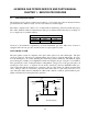
• The operator attempted to filter oil or shortening that was not heated. Cold oil and shortening are thicker and cause the pump motor to work harder and overheat. If the motor tries to run but the pump does not, there is a blockage in the pump. Incorrectly sized or installed paper will allow food particles and sediment to pass through the filter pan and into the pump. When sediment enters the pump, the gears can bind up causing the motor to overload, again tripping the thermal overload.
The suction tube heater and flexible hose heater are wired directly into the 24VAC source. They remain energized as long as the unit is plugged in. Line VAC Return Line Heater Tapes 24 VAC Suction Tube (Pan) Heater Tape Micro-switches Pump Relay Coil Pump Motor M Pump Motor Switch Filter Magic Simplified Wiring Diagram 1.9.6 Leakage Problems Leakage of the frypot almost always will be due to improperly sealed high limit switches, thermostats/temperature probes, and drain fittings.
product button is pressed, the timing circuitry activates a coil in the basket lift relay to supply power to the motor. There are two types of basket lifts: the “bell crank” design, and the “modular” design A bell crank basket lift consists of a cam and bell crank that are connected to the basket lift arm by a flat metal link. The cam is attached to a drive motor. The motor rotates the cam, thus raising or lowering the lift arm linked to the bell crank.
A modular basket lift consists of a toothed rod to which the basket lift arm is attached, a reversibledrive gear motor, and a pair of roller activated microswitches. The gear motor engages the teeth in the rod, moving it up or down depending upon the direction of rotation of the motor. Microswitches at the upper and lower limits of movement stop the motor when the basket is in the full up or full down position and also reverse the direction of current flow thus reversing the motor direction.
230/240/250V Modular Basket Lift Assembly BINDING/JAMMING PROBLEMS Noisy, jerky or erratic movement of the lifts is usually due to lack of lubrication of the rods and their bushings. Apply a light coat of Lubriplate™ or similar lightweight white grease to the rod and bushings to correct the problem. Another possible cause of binding, in the case of modular basket lifts, is the improper positioning of the motor, which prevents the gear from correctly engaging the teeth in the rod.
ELECTRONICS PROBLEMS This category encompasses problems with the relays, microswitches, capacitors, resistors, interface board, wiring, and controls. Troubleshooting the electronics of both bell crank and modular basket lifts is simply a process of verifying current flow through the individual components up to and including the motor. Using a multimeter set to the 250 VAC range, check the connections on both sides of the component for the presence of 120 VAC.
Modular Basket Lift Simplified Wiring Diagram NOTE: References to right and left are from the rear of the fryer. RIGHT SIDE LEFT SIDE BLK BLK 12.5 μ F BRN 1 RED 1 RESISTORS (either 2 or 6 depending on voltage and date of manufacture) 12.5 μ F BRN 2 RED 2 12.
1.9.8 Interpretation of Digital Controller Lights Power light on, heat light cycling, trouble light off, and melt light on: • If fryer oil temperature is below 180ºF (82ºC), the lights indicate the unit is operating normally. • If the oil temperature is above 180ºF (82ºC) and the heat light continues to cycle as if in the melt cycle, this may indicate a defective probe circuit or low incoming 12VAC to the controller.
1.10.1 Troubleshooting the 24VAC Circuit in Units without Interface Boards Verify that the ON/OFF switch is in the ON positon. Is 24VAC present at the gas valve? No Is 24VAC present at the ON/OFF switch? No Probable cause is a failed 24-volt transformer. Yes Is the continuity of the ON/OFF switch OK (zero resistance in the ON position)? No Probable cause is a failed ON/OFF switch. No Probable cause is a failed thermostat.
1.10.2 Troubleshooting the 24 VAC Circuit in Units with Interface Boards Verify that the drain valve is fully closed, then turn the controller on. Which LEDs are lit? None GV LED (with or without other LEDs) 24V LED only Is 24VAC present on IFB 24V terminals? Yes No Probable cause is a failed 24-volt transformer. Probable cause is a failed interface board. No Is 24VAC present on J1 Pin 6? Yes Attempt to light pilot. If the pilot will not light, see Troubleshooting the Gas Valve on Page 1-33.
24V XFMR 24V INTERFACE BOARD LED 24V K3 LED GV J1-6 10 20-PIN TERMINAL BLOCK OPTIONAL DSS 19 20 NOTE: On units not equipped with a drain safety switch, a jumper connects pins 10 and 19.
1.10.3 Troubleshooting the Gas Valve Verify that gasmain street valve is open and fryer gasline cutoff valve is open. Verify gas valve is in ON position. Is 24VAC present at the gas valve? Problem is in the 24VAC circuit. See Troubleshooting the 24VAC Circuit on Pages 1-29 and 1-30. No Natural For which gas is the fryer configured? Propane Is incoming gas pressure 6-14" WC (1.49-3.49 kPa)? Problem is with fryer gas supply. Is incoming gas pressure 11-14" WC (2.74-3.
1.10.4 Troubleshooting the Thermostat Turn the fryer on and set the thermostat control knob to the maximum setting. Does the burner light? Is the thermostat properly calibrated? Yes No No Probable cause is a failed gas valve. Yes Is 24VAC present at the gas valve? Probable cause is a failed thermostat. No While it is still hot, inspect the thermostat body for damage. Inspect leads for fraying, burning, breaks, and/or kinks.
1.10.5 Troubleshooting the Temperature Probe While it is still in the frypot, inspect the probe body for damage. Inspect the leads for fraying, burning, breaks, and/or kinks. If probe is bent, dented, or cracked, or if the leads are damaged, replace the probe. Determine the temperature of cooking oil/shortening using a thermometer or pyrometer placed at the tip of the probe. Disconnect the 15-pin harness from the controller. Measure probe resistance using J2 Pins 13 and 14.
Probe Resistance Chart For use with 45 Series fryers manufactured with Minco Thermistor probes only.
1-36 RIGHT MICROSWITCH RIGHT BASKET LIFT MOTOR COMPUTER BASKET LIFT RELAY 6 PIN CONNECTOR INTERFACE BOARD FOR COMPUTER OR BASKET LIFT TIMER ONLY. SOUND DEVICE DISCONNECT PLUG LEFT MICROSWITCH LEFT BASKET LIFT MOTOR N TO FILTER BASKET LIFT TIMER BASKET LIFT RELAY N TO NEXT FRYER POWER SUPPLY WITHOUT BASKET LIFT.
1-37 INTERFACE BOARD SOUND DEVICE FOR COMPUTER OR BASKET LIFT TIMER ONLY.
1-38 TO FILTER TO FILTER TO BASKET LIFT (OPTIONAL) POWER MELT CYCLE SWITCH/LIGHT ON/OFF SWITCH SOUND DEVICE SAFETY DRAIN OPTION HEATING LIGHT TO NEXT FRYER TERMINAL BLOCK TO NEXT FRYER TERMINAL BLOCK THERMOCOUPLE SCREENED AREA FOR MELT CYCLE OPERATION DISCONNECT PLUG GAS VALVE OPERATING THERMOSTAT 8050534D CAPACITOR GAS VALVE HIGH LIMIT THERMOSTAT HIGH LIMIT THERMOSTAT THERMOCOUPLE OPERATING THERMOSTAT ON/OFF SWITCH MELT CYCLE TIMER HEATING LIGHT MELT CYCLE SWITCH/LIGHT PLAN WIRING
SEE INSET A-A FOR 50-2 FILTER PUMP MOTOR ON/OFF SWITCH 1 ST. FRYER - RIGHT OF FILTER PLAN WIRING DIAGRAM FOR FILTER MAGIC II (DIRECT) TO FRYER POWER SUPPLY FOR (DIRECT) UNITS INSET A-A PUMP RELAY INSET B-B PUMP HEATER 1 ST.
PLAN WIRING DIAGRAM 45 SERIES BASKET LIFT SYSTEM LEFT BASKET LIFT MOTOR LEFT MICROSWITCH RIGHT BASKET LIFT MOTOR RIGHT MICROSWITCH DISCONNECT PLUG MILLIVOLT FRYER WIRING 6 PIN CONNECTOR TO 120V OR 240V TRANSFORMER IN FRYER 6 PIN CONNECTOR DISCONNECT PLUG LEFT TIMER RIGHT TIMER 8050379E 1-40
PLAN WIRING DIAGRAM 45 SERIES BASKET LIFT SYSTEM LEFT BASKET LIFT MOTOR LEFT MICROSWITCH RIGHT BASKET LIFT MOTOR RIGHT MICROSWITCH DISCONNECT PLUG MILLIVOLT FRYER WIRING 6 PIN CONNECTOR TO 120V OR 240V TRANSFORMER IN FRYER 6 PIN CONNECTOR DISCONNECT PLUG LEFT TIMER RIGHT TIMER 8050379E 1-41
THIS PAGE INTENTIONALLY LEFT BLANK.
45 SERIES GAS FRYERS SERVICE AND PARTS MANUAL CHAPTER 2: PARTS LIST ACCESSORIES 1 4 3 2 5 6 7 14 8 9 10 11 12 13 ITEM 1 2 3 * * 4 * 5 6 7 8 9 10 11 12 PART # 803-0271 803-0099 803-0132 803-0136 803-0103 806-5518 826-0993SP 823-1885 910-4617 910-2285 910-7515 910-7443 910-7515SP 910-2572 806-1698SP 806-1699 13 810-0074 14 810-0073 * Not illustrated.
6 36 1 23 9 5 11 12 5 27 37 2-2 20 28 30 29 33 24 22 24 17 14 31 32 35 15 16 25 7 16 19 15 13 17 21 23 2 4 11 18 10 3 26 34 BASKET LIFT ASSEMBLIES AND COMPONENT PARTS Bell Crank Basket Lift
ITEM 1 2 3 4 5 6 7 8 9 10 11 12 13 14 15 16 17 18 19 20 21 22 23 24 25 26 27 28 29 30 31 32 33 34 35 36 37 PART # 807-0107 807-0108 807-0124 807-0240 826-1680 826-1358 809-0050 809-0063 809-0076 809-0082 809-0097 809-0113 809-0127 826-1370 809-0155 809-0196 826-1381 809-0360 826-1374 809-0480 810-0045 810-0052 810-0170 810-0172 810-0192 810-0220 812-0138 813-0035 823-1419 900-4110 910-0119 910-3177 910-3783 910-9361 920-3233 920-6076 823-06931 823-06932 COMPONENT Gear Motor, Basket Lift 120VAC 240VAC Bush
9 6 19 15 2-4 23 (After 10/02) 5 208-250V Configuration 1 14 100-120V Configuration 2 26 7 5 10 14 13 12 21 20 (Before 11/02) 11 5 3 8 13 16 14 17 4 22 12 18 24 14 NOTES: 1. Assemblies 106-1807SP (100-120V) and 106-1810SP (208-250V) do not include Items 8, 16, 24, 25, and 26. These items must be ordered separately. 2. For 100-120V units, each individual resistor (807-2661) may be replaced or the entire reistor assembly (806-8530SP) may be replaced. 3.
ITEM 1 2 3 4 5 6 7 8 9 10 11 12 13 14 15 16 17 18 19 20 21 22 23 24 25 26 PART # 200-2942 900-7655 806-5964SP 807-2133 807-2572 806-8530SP 106-2771 809-0082 826-1361 809-0127 809-0186 826-1366 809-0247 826-1359 826-1371 826-1374 809-0503 810-0172 810-1012 812-0442 813-0035 816-0033 900-5529 901-8499 902-8499 910-4776 823-06931 823-06932 COMPONENT Mount, Modular Basket Lift** For use on units with 12-pin connectors For use on units with 6-pin connectors Motor Assembly, Modular Basket Lift*** Capacitor, 1
BURNER ASSEMBLY COMPONENT PARTS 9 10 1 4 3 11 5 8 6 NOTE: Red dot indicates Propane/Butane Pilot Assembly; green dot indicates Manufactured Gas; no dot indicates Natural Gas. Robertshaw gas valves (illustrated above) are no longer available. Order kit 826-1596 to replace natural gas valves, 826-1597 to replace propane gas valves, or 826-1643 to replace manufactured gas valves.
ITEM 1 2 3 4 PART # 806-0225SP 826-1155 807-1906 810-1001 823-0496 810-0407 826-1357 826-1386 810-0361 810-0131 812-1301 810-0343 826-1387 810-0952 810-0339 812-0914 812-1302 812-0444 5 6 7 810-1830 806-8688SP 810-0426 810-0616 810-1773 806-8689SP 810-0427 810-0683 823-0574 810-1873 826-1527 812-1284 8 9 10 * 810-0705 812-0278 810-0691 810-0975 807-3294 807-3295 807-3354 810-0353 11 806-6710SP 806-6711SP * Not illustrated.
CABINET ASSEMBLIES AND COMPONENT PARTS MJ145, F145 (Filter Ready), and Spreader Cabinet Assembly Components 5 7 3 4 2 2 6 1 8 Spreader Cabinet (Typical) 1 Fryer Cabinet (Typical) See Page 2-9 for access opening covers. 9 9 NOTES: Fryer and spreader cabinet assemblies are identical except for the backs — spreader backs do not have a formed edge at the top.
MJ45 Batteries 8 9 6 4 10 7 3 1 2 5 (MJ345 ILLUSTRATED IS TYPICAL OF ALL) NOTE: See Page 2-14 for casters, legs and associated hardware.
FM45 Batteries with Built-In Filtration 1 NOTE: Items 1-15 are used in all FM45 Builit-In Filter configurations and therefore are not repeated for the FM245 and FM145 (Filter on Right) illustrations. 2 4 3 15 7 6 5 22 9 10 28 11 FM145 (FILTER ON LEFT) (All components except Items 27 and 28 are the same for FM245 and FM345 units with the filter on the left.
ITEM 1 2 3 4 5 6 PART # 910-7480 806-8274SP 900-7277 910-7274SP 900-7274SP 900-4089 910-6983SP 900-6983SP 7 911-9323SP 901-9323SP 8 9 10 11 12 13 14 15 16 17 18 19 20 21 22 23 24 25 26 27 912-9323SP 902-9323SP 900-7414 900-6979SP 809-0413 900-4391SP 826-1379 900-1700 900-7314SP 910-1601 900-1621 901-1599 901-1595 902-1599 902-1595 901-4390 902-4390 806-4917 900-4426 900-4383 900-2394 900-2395 900-2396 28 29 900-1631 900-7243 900-9319 900-1630 900-7244 900-9322 900-7242 900-9321 900-9320 826-1374 COMP
Filter Magic II Add-On Cabinet Components 31 30 3 29 4 29 2 18 9 1 25 24 20 23 10 22 19 15 14 16 12 17 21 13 14 25 26 27 ADD-ON FILTER MAGIC CABINET 18 28 18 8 7 6 5 20 11 22 15 14 16 12 17 21 13 18 UNDERCOUNTER ADD-ON FILTER MAGIC CABINET 14 2-12
ITEM 1 PART # 911-9324SP 901-9324SP 2 912-9324SP 902-9324SP 3 910-7274SP 900-7274SP 4 910-4089 900-4089 5 911-7677SP 901-7677SP 6 912-7677SP 902-7677SP 7 8 9 10 11 12 13 14 15 16 17 18 19 20 910-4786 900-4786 910-7680 900-4813SP 900-4391SP 900-4785 806-5317SP 806-4897SP 900-1621 910-1601 810-0007 910-1832 826-1374 826-1379 910-0889 900-0889 21 22 23 24 25 26 27 28 29 30 31 910-0890 900-0890 809-0359 900-7414 900-4175 826-1362 809-0429 809-0191 810-0665 900-7277 806-8274SP 910-7480 COMPONENT Side, Left
CASTERS, LEGS, AND ASSOCIATED HARDWARE 1 6 ITEM PART # 1 823-2669 2 826-1130 3 826-1118 4 826-1117 5 826-1138 6 826-1237 7 826-1115 8 826-1095 9 826-0900 * 826-1113 * 826-1098 * 826-1043 * Not illustrated.
COMPONENT SHIELDS, FILTER BOX ASSEMBLIES, AND COMPONENT PARTS 4 6 7 8 2 4 2 6 7 3 8 17 3 18 20 21 9 11 9 3 13 12 3 3 14 15 16 10 5 5 1 1 Non-CE Shields CE Shield 19 20 21 Component Shield Assemblies with Interface Boards ITEM PART # 806-4773SP 806-4775SP 806-6629SP 1 2 3 4 5 * 6 7 8 9 10 11 12 900-4340 824-0161 809-0360 806-3548 806-7505 807-1582 810-2243 809-0349 809-0096 809-0250 807-2469 810-0045 807-0855 807-0979 807-0800 807-0680 13 807-1999 14 807-0066 15 809-0097 1
19 17 13 18 10 14 13 2 20 3 4 1 100-120V Non CE Electromechanical timer shown for identification purposes only. This timer has been replaced by Items 17, 18, and 19 (shown in the 100120V illustration) in all applications. 13 16 14 11 13 20 2 3 4 1 208-240V Non-CE NOTE: Melt cycle timers (Items 16 and 17) are not present in shield assemblies 806-4774SP, 806-4776SP, and 806-6630SP.
ITEM PART # 806-4774SP 806-4776SP 806-4772SP 806-4777SP 806-6630SP 806-6632SP 1 2 3 4 5 6 7 8 9 10 11 900-4340 807-0066 809-0097 826-1358 816-0217 810-1164 810-1168 826-1359 826-1366 807-0800 807-0680 807-2180 * 807-1597 12 807-1999 13 826-1374 14 810-0045 15 807-2469 16 826-1546 17 806-9613 18 900-8741 19 809-0580 20 807-0156 * Not illustrated.
Filter Boxes 3 13 16 17 or 14 16 4 5 2 17 1 19 19 3 4 5 6 7 17 13 18 7 14 17 18 17 or Non-CE Standard 6 16 15 16 16 17 17 19 CE Standard 3 8 9 11 PART # 806-4359SP 806-4360SP 806-6709SP 806-4361SP 806-4362SP 1 2 3 4 5 6 7 8 9 10 11 12 13 14 15 16 17 18 19 200-0409 200-0410 807-0012 809-0096 826-1358 807-0276 809-0097 816-0217 810-1164 810-1168 826-1359 826-1366 807-0800 807-0680 807-1999 809-0103 809-0050 807-0124 809-0360 4 5 12 18 ITEM Non-CE Undercounter 10
THIS PAGE INTENTIONALLY LEFT BLANK 2-19
23 26 24 20 14 28 30 29 19 18 9 10 11 12 13 8 21 15 25 7 5 22 16 6 1 5 6 2 17 27 5 6 3 5 6 4 CONTROL PANEL ASSEMBLIES, FLUE CAPS, TOP CAPS, and RELATED ITEMS 2-20
ITEM 1 * 2 3 4 5 6 7 8 9 10 11 12 13 14 PART # 810-1403 809-0921 823-1462 106-2185 809-0171 826-1351 806-9257SP 910-8284 826-1334 809-0190 810-0374 810-0194 809-0047 910-5018 910-6545 823-3749 15 823-2540 823-3536 16 823-2541 823-3537 17 823-2569 18 900-5486 19 900-4253 20 824-0404 21 824-0405 22 824-0406 23 824-0407 24 806-4732SP 25 806-4733SP 26 806-4734SP 27 806-5018SP 28 910-8503 29 910-8505 30 910-3557 * 826-1379 * 826-1371 * Not illustrated.
CONTROLLER ASSEMBLIES (Thermostat Controllers) CONTROLLER WITHOUT TIMERS 26 12 13 2 9 10 11 1 14 CONTROLLER WITH MECHANICAL TIMERS 27 2 17 12 13 6 3 4 1 15 9 10 11 16 17 CONTROLLER WITH ELECTRIC TIMERS 2 NOTE: Thermostat shaft and associated components are the same for all configurations.
ITEM 1 2 3 4 5 6 7 8 9 10 11 12 13 14 15 PART # 802-0765 802-1470 802-1473 910-1551 810-0334 810-1287 810-1822 810-1823 807-1525 807-3498 807-3575 826-1395 826-1338 810-0585 826-1552 807-0401 16 950-0246 17 809-0093 18 810-0276 19 810-0999 20 809-0157 21 826-1361 22 809-0050 23 900-2241 24 900-2071 25 826-1371 26 910-4345 27 910-4344 * 802-0336 * 806-4797 * Not illustrated.
CONTROLLER ASSEMBLIES (Other than Thermostat Controllers) 1 2 3 4 SOLID STATE ITEM 1 2 3 PART # 106-1149SP 106-1199SP 106-1216 106-1218 106-1230 106-2079SP 106-1501 106-1505 4 806-3559 * 910-3690 * 806-3660 * 826-1379 * 826-1032SP * Not illustrated.
DOOR ASSEMBLY 1 5 4 2 7 3 6 5 ITEM PART # 806-8320 806-6405SP 1 106-0554SP 2 826-1343 3 810-1422 4 826-1379 5 810-1508 6 824-0616SP 7 900-4807 * 810-1105 * Not illustrated.
8 3 12 1 33 2 2-26 22 11 13 4 10 9 23 7 5 Compression washers 31 24 Steel flat washer over plastic washer 32 6 30 29 25 26 27 28 14 19 20 21 17 18 15 DRAIN AND FILTRATION SYSTEM COMPONENTS Drain System Components
Item * 1 2 3 4 5 6 7 8 9 10 * 11 Part # 826-0877 810-0396 809-0071 826-1375 816-0032 826-1348 816-0021 826-1382 900-0757 823-0717 823-0718 813-0284 Component Kit, Clamp Service (Contains 2 each of Items 1-3 and 1 of Item 4) Clamp Section (Requires 2 per connection) Nut, ¼–20 Screw, 10–32 X ¾ Seal (Connection Gasket) Cover, Clean-out (Pkg. of 5) Gasket, Clean-out Wing Nut, Clean-out Cover Retaining (Pkg. of 10) Cover, Drain End Full Vat, 15.5-inches Long End, Full Vat, 8.
Filter Magic II Filter Pan Assemblies 4 9 1 10 9 5 12 11 10 3 11 7 Fitting on outside bottom of inner pan. 8 8 7 6 A Item A B 1 2 3 4 5 6 * * * Part # 806-9255SP 823-2751SP 806-6093SP 806-4338SP 823-1360SP 806-5282SP 823-1731SP 823-1361 824-0291 910-1350 816-0117 806-4373 811-0861 811-0746 7 810-0005 8 810-0006 9 824-0416 10 810-1406 11 900-8827 12 810-0180 * 803-0170 * 803-0002 * Not illustrated.
FRYPOT ASSEMBLIES AND COMPONENT PARTS 15 1 5 10 16 12 2 11 4 3 16 11 6 14 13 7 8 ITEM 1 PART # 106-2549SP 806-3810SP 2 3 4 5 6 7 8 9 10 11 12 13 14 15 16 17 18 823-3887SP 823-0921SP 806-5778SP 810-0424 806-5567SP 806-1095SP 809-0409 810-0647 900-1090 806-5566SP 900-6441 812-0249 812-0248 816-0602 812-0269 826-1374 809-0173 809-0170 9 17 18 12 COMPONENT Frypot Assemblies, Complete (Items 2, 3, 5, 6, and 10-18) Stainless Steel Cold Rolled Steel Frypot Assembly, without Insulation Stainles
2-30 14 18 19 4 17 2 15 16 Detail of Motor, Pump, and Disconnect Components 1 10 13 12 6 11 7 8 3 8 4 5 8 8 20 8 9 9 8 Item shown disproportionately large for clarity.
ITEM 1 PART # 826-1712 826-1756 826-1270 * 806-6728SP 2 826-1264 3 813-0265 4 813-0062 5 813-0368 6 813-0156 7 813-0003 8 810-1057 * 810-1668 9 813-0275 10 810-0278 11 902-0883 12 813-0165 13 813-0022 14 823-1356 15 826-1392 16 816-0102 17 900-1472 18 910-1627 19 813-0330 20 806-4694SP * 813-0117 * 807-1600 * 807-1601 * 807-1598 * 807-1599 * 807-2016 * 807-1408 * 807-2050 * 811-0746 * Not illustrated COMPONENT Pump Motor 100-120 VAC 50/60Hz (includes gasket 816-0093) 208 VAC 50/60 Hz (includes gasket 816
THROUGH MARCH 2001 APRIL 2001 AND LATER 10 6 6 7 12 21 11 13 20 18 19 15 10 8 15 1 16 8 12 2 3 9 13 11 14 1 10 9 11 3 14 16 22 17 4 5 5 ITEM 1 2 3 4 5 6 7 8 9 10 11 12 13 14 15 16 17 18 19 20 21 22 PART # 807-2103 930-0839 810-1999 900-1853 814-0047 900-0239 920-0220 809-0200 826-1381 810-0220 809-0142 809-0056 809-0104 809-0247 826-1359 826-1366 200-0938 810-1165 810-0285 200-1059 809-0601 200-0821 COMPONENT Microswitch Bracket, Microswitch Bracket, Valve Handle Handle, Oil Retu
POWER SHOWER ASSEMBLY 5 1 4 2 ITEM 1 2 3 4 5 PART # 806-4503SP 809-0415 826-1344 826-1390 814-0001 3 COMPONENT Power Shower Assembly, Complete Screw, Cleanout O-Ring (Pkg of 5) Seal (Gasket) (Pkg of 5) Grip, Handle 2-33
TEMPERATURE PROBE, THERMOSTATS, AND RELATED COMPONENTS 9 1 2 4 3 5 8 4 7 ITEM 1 2 3 4 5 6 7 8 9 PART # 806-4206 826-1177 806-7550 807-2274 807-0280 812-1256SP 806-3910 806-0183 210-0681 6 COMPONENT Temperature Probe, Minco Thermostat, Non-CE 425°F High-Limit (see NOTE 1) Thermostat, CE 218°C High-Limit (see NOTE 2) Thermostat, High Limit Adapter, High-Limit Thermostat (used only with Robertshaw gas valves) Adapter Kit, High-Limit Thermostat to Honeywell Gas Valve Thermostat Assembly, Navy High-Li
WIRING ASSEMBLIES/HARNESSES AND REMOTE CABLE ASSEMBLIES 806-2079SP 806-8555SP 106-1822SP 106-1804SP 806-4798SP 806-6708SP 807-3699 806-9777SP 806-9778SP 806-9779SP 806-9780SP 806-9781SP 826-1560 806-3549SP 806-6705SP 806-4214SP 806-4215SP Wiring Assemblies and Harnesses 100-120V Basket Lift Universal Motor (6-Pin female w/6 wires plus 1 separate wire) 208-240V Modular Basket Lift Motor (6-Pin female w/6 wires plus 4 separate wires) 100-120V Modular Basket Lift Motor (12-pin female w/5 wires) 208-250V Modul
WIRING CONNECTORS, PIN TERMINALS, AND POWER CORDS 1 6 11 ITEM PART # * * * 807-0154 806-6229SP 807-1685 1 807-1068 2 807-0158 3 807-0156 5 807-0159 5 807-0875 6 807-1067 7 807-0157 8 807-0155 9 807-0160 10 807-0804 11 826-1341 12 826-1342 13 807-2518 * Not illustrated.
THIS PAGE INTENTIONALLY LEFT BLANK.
Frymaster, L.L.C.