FBR18 & FBRA18 Series Gas Rethermalizers Installation, Operation, Service, and Parts Manual Frymaster, a member of the Commercial Food Equipment Service Association, recommends using CFESA Certified Technicians.
NOTICE IF, DURING THE WARRANTY PERIOD, THE CUSTOMER USES A PART FOR THIS ENODIS EQUIPMENT OTHER THAN AN UNMODIFIED NEW OR RECYCLED PART PURCHASED DIRECTLY FROM FRYMASTER/DEAN, OR ANY OF ITS AUTHORIZED SERVICE CENTERS, AND/OR THE PART BEING USED IS MODIFIED FROM ITS ORIGINAL CONFIGURATION, THIS WARRANTY WILL BE VOID.
DANGER Improper installation, adjustment, maintenance or service, and unauthorized alterations or modifications can cause property damage, injury, or death. Read the installation, operating, and service instructions thoroughly before installing or servicing this equipment. Only qualified service personnel may convert this appliance to use a gas other than that for which it was originally configured. See Chapter 1 of this manual for definition of qualified service personnel.
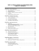
FBR18 & FBRA18 SERIES GAS RETHERMALIZERS TABLE OF CONTENTS CHAPTER 1: General Information 1.1 Parts Ordering and Service Information ............................................................................1-1 1.2 Safety Information .............................................................................................................1-1 1.3 Equipment Description ......................................................................................................1-2 1.
6.2 6.3 6.4 6.5 6.6 6.6.1 6.6.2 6.6.3 6.6.4 6.6.5 6.6.6 6.6.7 6.6.8 6.6.9 6.7 6.7.1 6.7.2 6.7.3 6.8 6.8.1 6.8.2 6.8.3 6.8.4 6.9 6.10 Temperature Probe ............................................................................................................ 6-3 Water Level Sensors (FBRA18 Only)............................................................................... 6-3 Accessing the Rethermalizer for Servicing .......................................................................
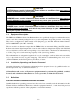
FBR18 & FBRA18 SERIES GAS RETHERMALIZERS CHAPTER 1: GENERAL INFORMATION 1.1 Parts Ordering and Service Information In order to assist you as quickly as possible, the Frymaster Factory Authorized Service Center (FASC) or Service Department representative requires certain information about your equipment. Most of this information is printed on a data plate affixed to the inside of the door. Parts orders may be placed directly with your local FASC or distributor.
CAUTION CAUTION boxes contain information about actions or conditions that may cause or result in a malfunction of your system. WARNING WARNING boxes contain information about actions or conditions that may cause or result in damage to your system, and which may cause your system to malfunction. DANGER DANGER boxes contain information about actions or conditions that may cause or result in injury to personnel, and which may cause damage to your system and/or cause your system to malfunction. 1.
QUALIFIED INSTALLATION PERSONNEL Qualified installation personnel are individuals, or firms, corporations, or companies which, either in person or through a representative, are engaged in and are responsible for the installation of electrical and gas appliances. Qualified personnel must be experienced in such work, be familiar with all electrical precautions involved, and have complied with all requirements of applicable national and local codes.
FBR18 & FBRA18 SERIES GAS RETHERMALIZERS CHAPTER 2: INSTALLATION INSTRUCTIONS 2.1 General Installation Requirements PROPER INSTALLATION IS ESSENTIAL FOR EFFICIENT, TROUBLE-FREE OPERATION OF YOUR RETHERMALIZER. ANY UNAUTHORIZED ALTERATIONS MADE TO THIS EQUIPMENT WILL VOID THE Frymaster WARRANTY. Upon arrival, inspect the rethermalizer carefully for visible or concealed damage. (See Shipping Damage Claim Procedure in Chapter 1.
This equipment is manufactured to use the type of gas specified on the rating plate attached to the door. Connect equipment stamped “NAT” only to natural gas and that stamped “PRO” only to LP (Propane) gas. Installation shall be made with a gas connector that complies with national and local codes. Quick disconnect devices, if used, shall likewise comply with national and local codes.
After the unit has been positioned in the area where it will be used, ensure the following has been accomplished before connecting the unit to the gas supply: 1. Adequate means must be provided to limit the movement of this equipment without depending upon the gas line connections. If a flexible gas hose is used, a restraining cable must be connected at all times when the equipment is in use. 2.
2.4 Connecting to the Gas Supply GAS CONNECTIONS AND PIPE SIZES The size of the gas supply pipe is very important. If the pipe is too small, the gas pressure at the burner manifold will be low. This will cause slow recovery and delayed ignition. The incoming gas supply line should be a minimum of 1½ inches (38mm) ID.
WARNING “Dry-firing” this equipment will cause damage to the cookpot. Always ensure that the cookpot is filled with water before firing your unit. 4. It is suggested that the burner manifold pressure be checked at this time by the local gas company or an authorized service agent. Refer to “Check Burner Manifold Pressure” in Chapter 4 of this manual for the proper procedure. 2.5 Converting to Another Gas Type This equipment is configured at the factory for either natural gas or LP (Propane) gas.
FBR18 & FBRA18 SERIES GAS RETHERMALIZERS CHAPTER 3: OPERATING INSTRUCTIONS 3.1 Introduction Mechanically, the FBR18 and FBRA18 rethermalizers are virtually identical, the only difference being that the FBRA18 units have an automatic filling (AutoFill) feature. Both units use the same digital temperature controller and mechanical timers. In operation, a setpoint is programmed into the controller which then regulates burner firing to maintain the water in the cookpot at the desired temperature.
NOTE: The unit comes from the factory configured to display in degrees Fahrenheit. To toggle back and forth between Fahrenheit and Celsius, press the Celsius/Fahrenheit display switch. 2. The controller will automatically cycle the burners on and off seven times or until the temperature in the cookpot reaches 160°F (71°C), whichever comes first. At that time, it will enter the continuous heat mode.
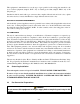
OFF ON Honeywell 1. Turn the gas valve to the ON position (see illustration below). 2. Press the controller Power switch. On FBR18 models, the burners will light for several seconds then go out. A few seconds later they will light again. This cycle will repeat seven times or until the water in the cookpot reaches 160°F (71°C), whichever comes first, at which time the burners will remain lit until the setpoint is reached.
4. After the solution simmers for an hour, turn the unit off, allow the solution to cool, then add 2 gallons (7.75 liters) of cold water and stir. Drain the solution and clean the cookpot thoroughly. 5. Rinse the cookpot at least twice by filling with clean water and draining. 6. Reprogram the setpoint to the appropriate temperature. 3.5 Shutting Down the Rethermalizer 1. Turn the unit off by pressing the Power switch. OFF ON Honeywell 2.
FBR18 & FBRA18 SERIES GAS RETHERMALIZERS CHAPTER 4: PREVENTIVE MAINTENANCE 4.1 Daily Checks and Services Inspect Rethermalizer and Accessories for Damage Look for loose or frayed wires and cords, leaks, foreign material in cookpot or inside cabinet, and any other indications that the rethermalizer and accessories are not ready and safe for operation. Clean Cabinet Inside and Out Clean inside the cabinet with a dry, clean cloth.
4.2 Quarterly Checks and Services Check Digital Controller Set Point Accuracy 1. Fill the cookpot with water. Press the controller power switch. When the Heat Mode indicator (decimal between the first and second digits of the display) goes out, insert a good-grade thermometer or pyrometer probe into the cookpot, with the end touching the temperature probe at the lower front centerline of the cookpot and wait one minute. 2.
open or close the air intake opening until a bright orange-red glow is obtained. Carefully hold the plate in position and retighten the nut(s). Clean Gas Valve Vent Tube 1. Set the rethermalizer power switch and the gas valve to the OFF position. 2. Carefully unscrew the vent tube from the gas valve. NOTE: The vent tube may be straightened for ease in removal. Vent Tube 3. Pass a piece of ordinary binding wire (.052 inch diameter) through the tube to remove any obstruction. 4.
3. Place the gas valve in the ON position. Place the controller power switch in the ON position. When the burner lights and continues to burn, compare the indicated pressure to the table below. Burner Manifold Gas Pressures Gas Natural LP Pressure 3.5" W.C. 0.8 kPa 8.25" W.C. 2.5 kPa 4. If necessary, adjust the burner gas pressure by removing the cap from the gas valve regulator and turning the regulator screw to obtain the correct pressure. When the correct pressure is obtained, reinstall the cap. 5.
FBR18 & FBRA18 SERIES GAS RETHERMALIZERS CHAPTER 5: OPERATOR TROUBLESHOOTING 5.1 Introduction This chapter provides an easy reference guide to the more common problems that may occur during the operation of your equipment. The troubleshooting guides in this chapter are intended to help you correct, or at least accurately diagnose, problems with your equipment. Although the chapter covers the most common problems reported, you may very well encounter a problem not covered.
5.2 Troubleshooting Guides COOKPOT DID NOT FILL WHEN UNIT WAS TURNED ON. WATER SUPPLY TO UNIT VERIFIED TO BE ON. NOTE: This guide applies to FBRA18 units only. Controller is not functioning. Probable causes are failed 12V transformer, failed interface board, or failed controller. Did anything appear in controller display when unit was turned on? No Yes Open control panel by removing screws in each upper corner.
WATER DID NOT SHUT OFF WHEN COOKPOT WAS FULL. NOTE: This guide applies to FBRA18 units only. Use bottlebrush to clean water level sensors. Problem resolved. Yes Did water stop? No Add 1/8 cup of salt to water in cookpot and stir. Mineral content of water is insufficient for water sensor to detect it. Whenever cookpot is refilled, add 1/8 cup of salt. Yes Did water stop? No Open control panel by removing screws in each upper corner.
WATER NOT HEATING. AUTOFILL (IF INSTALLED) WORKED PROPERLY. Press the Temperature Check button twice to display setpoint. Has the correct setpoint been programmed? No Program setpoint in accordance with instructions in Chapter 3. Yes Did burners light? Refer to troubleshooting guide "BURNERS DO NOT LIGHT". No Yes Did water reach setpoint temperature? No Insert a good grade thermometer into cookpot with tip near temperature probe and wait two minutes.
BURNERS DO NOT LIGHT. Verify that correct setpoint has been programmed, that main gas supply valve is open, and that equipment gas valve is set to ON. Press ON/OFF button. Did burners light? Yes Problem resolved. No Use bottlebrush to clean low water sensor. If burners still do not light, remove the cover over the water sensors and thoroughly clean them with a Scotchbrite or similar nylon pad. Did burners light? Yes Problem resolved. No Open control panel by removing screws in each upper corner.
5.3 Replacing the Controller or Controller Wiring Harness 1. Disconnect the rethermalizer from the electrical supply. 2. Remove the two screws in the upper corners of the control panel and swing the panel open from the top, allowing it to rest on its hinge tabs. 3. Disconnect the wiring harness from the back of the controller. If replacing the harness, disconnect it from the interface board, install the new harness, and then reverse steps 1 and 2 to complete the process. 4.
FBR18 & FBRA18 SERIES GAS RETHERMALIZERS CHAPTER 6: SERVICE PROCEDURES 6.1 Functional Description These rethermalizers contain a welded stainless steel cookpot that is directly heated by a high efficiency burner system requiring approximately 43% less energy than conventional burner systems to heat the same volume of water. Two self-contained combustion chambers (referred to as “burners”) are located beneath the cookpot.
guished), current to the ignition module is cut, preventing the main valve from opening, and the ignition module “locks out” until the power switch is turned off and then back on. A probe monitors the temperature in the cookpot. When the programmed setpoint temperature is reached, resistance in the probe causes the heat cycle circuitry in the controller to cut off current flow through the heat relay. This in turn cuts off the 24 VAC to the ignition module, causing the gas valve to close.
The relays in earlier design boards are soldered on and cannot be replaced. Later design boards feature replaceable plug-in relays. In earlier designs boards, a heat relay (K2) switches 24VAC to the ignition and gas valve circuits when the controller heat logic circuit calls for heat. Simultaneously, a blower motor relay (K4) switches 120VAC to the blower motor. In later design boards, relay K3 serves as both the heat relay and blower motor relay.
6.2 Accessing the Rethermalizer for Servicing DANGER Moving a rethermalizer filled with hot water may cause spilling or splattering of the hot water. Always drain the cookpot before attempting to relocate the unit for servicing. 1. Shut off the gas supply to the unit. Unplug the electrical power cord. Disconnect the unit from the gas supply. 2. Remove any attached restraining devices. 3. Relocate the rethermalizer for service accessibility. 4.
6.6 Replacing Components 6.6.1 Replacing the Controller or Controller Wiring Harness Refer to Chapter 5, Section 5.3 for this procedure. 6.6.2 Replacing the Temperature Probe 1. Unplug the rethermalizer and drain the cookpot. 2. Remove the screws from the upper corners of the timer panel and swing the panel open from the top, allowing it to rest on its hinge tabs. Cut the probe leads off at the rear of the probe. NOTE: Once the probe leads have been cut, the probe cannot be reused.
5. On FBRA18 models only, mark the water level sensor wires and disconnect them from terminals J1-1 (upper sensor) and J1-2 (lower sensor). 6. Remove the nuts in each corner of the interface board and carefully pull the board off the mounting studs, being careful not to dislodge the spacers on the studs. 7. Position the replacement board on the studs and replace the four nuts. 8. Reconnect the water level sensor wires (FBRA18 models only) and the 12-pin connector to the interface board. 9.
6.6.6 Replacing the Combustion Air Blower Refer to Chapter 4, Section 4.4, Clean Combustion Air Blower, for instructions on removing and reinstalling the combustion air blower. 6.6.7 Replacing the Gas Valve 1. Turn off the gas supply to the rethermalizer, unplug the unit, and drain the cookpot. 2. Disconnect the unit from the gas supply line and remove any fitting that may be attached to the gas manifold at the rear of the unit. 3. Disconnect the gas lines at each burner orifice. 4.
4. Remove the four screws from the blower stabilizing bracket attached to the blower assembly and to each burner. Remove the stabilizing bracket from the unit. 5. Remove the screw securing the blower support bracket to the cookpot assembly and lower the blower assembly out of the way. It is not necessary to disconnect the blower wiring. 6. Remove the two screws at the front of the burner assembly to be replaced, then pull the assembly toward the front of the unit slightly to free it from its rear support.
knowledge of possible problems, and the probable causes of each. With this knowledge, the technician should be able to isolate and correct any problem encountered. Problems that are likely to be encountered can be grouped into five broad categories: 1. Ignition failures 2. Improper burner functioning 3. Improper temperature control 4. Controller-related problems 5. Autofill system problems. The probable causes of each category are discussed in the following sections.
tion failure situation may be encountered in which all components appear to be serviceable and the microamp reading is within specification, but the unit nevertheless goes into ignition failure during operation. The probable cause in this case is an intermittent failure of an ignition module. When the unit is opened up for troubleshooting, the module cools down enough to operate correctly, but when the unit is again closed up and placed back into service, the module heats up and fails.
If popping is consistent during all hours of operation, the most likely cause is an insufficient air supply. Check for “negative pressure” conditions in the kitchen area. If air is flowing into the kitchen area, this indicates that more air is being exhausted than is being replenished, and the burners may be starved for air. If the rethermalizer’s gas and air supplies are okay, the problem is most likely with one of the electrical components.
6.7.3 Improper Temperature Control Temperature control is a function of several interrelated components, each of which must operate correctly. The principle component is the temperature probe. Other components include the interface board, the water level sensors (on FBRA18 units), the controller, and the ignition module. Whatever the cause, the symptom is failure of the unit to attain or maintain setpoint temperature.
6.8.1 Troubleshooting the Gas Valve NOTE: All voltage measurements must be made within 4 seconds of unit calling for heat. If unit does not fire within 4 seconds, ignition modules will lock out and controller must be turned off then back on to reset. MAIN GAS SUPPLY VALVE VERIFIED TO BE OPEN AND EQUIPMENT GAS VALVE IN ON POSITION. Is there 24VAC on gas valve main coil (PV terminal)? Problem is with 24VAC circuit. Refer to Troubleshooting the 24VAC Circuit.
6.8.2 Troubleshooting the 24 VAC Circuit in FBR18 Units NOTE: All voltage measurements must be made within 4 seconds of unit calling for heat. If unit does not fire within 4 seconds, ignition modules will lock out and controller must be turned off then back on to reset. UNIT IS CONNECTED TO POWER SUPPLY, DRAIN VALVE IS FULLY CLOSED, CONTROLLER IS ON AND IS CALLING FOR HEAT (decimal appears between first two digits in controller display).
THE 24 VAC CIRCUIT IN FBR18 UNITS 24V TRANSFORMER J3 PIN 8 LED 3 (24V) RELAY K2 ON EARLY DESIGN BOARDS OR RELAY K3 ON LATER DESIGN BOARDS LED 4 (PWR) RIGHT PWR TERMINAL J2 PIN 7 BLOWER CENTRIFUGAL SWITCH RIGHT IGNITION MODULE J2 PIN 5 V1S TERMINAL LED 2 (PWR) LEFT PWR TERMINAL J2 PIN 2 LEFT IGNITION MODULE J2 PIN 4 V2S TERMINAL LED 5 (GV) J3 PIN 9 GAS VALVE 6-15
6.8.3 Troubleshooting the 24 VAC Circuit in FBRA18 Units UNIT IS CONNECTED TO POWER SUPPLY, DRAIN VALVE IS FULLY CLOSED, NO WATER IS IN POT, CONTROLLER IS ON. Is POWER LED lit? Go to "A". No Yes Is WATER LED lit? Ensure upper water level sensor is not grounded (i.e., 24VAC present across sensor and cabinet). If sensor is not grounded, most probable cause is failed interface board.
6.8.3 Troubleshooting the 24 VAC Circuit in FBRA18 Units (Continued) NOTE: All voltage measurements involving the gas valve leg of the 24V circuit must be made within 4 seconds of unit calling for heat. If unit does not fire within 4 seconds, ignition modules will lock out and controller must be turned off then back on to reset. A Is 24VAC present on N/O terminal of latch relay? Probable causes are failed 24V transformer or failed wiring between transformer box and component box.
6.8.3 Troubleshooting the 24 VAC Circuit in FBRA18 Units (Continued) NOTE: All voltage measurements involving the gas valve leg of the 24V circuit must be made within 4 seconds of unit calling for heat. If unit does not fire within 4 seconds, ignition modules will lock out and controller must be turned off then back on to reset. B Is 24VAC present across the gas valve main coil (PV) terminal? Yes Gas valve leg of 24V circuit is OK.
6.8.3 Troubleshooting the 24 VAC Circuit in FBRA18 Units (Continued) C Is 24VAC present on J1 pin 5 when unit calls for heat? NOTE: All voltage measurements must be made within 4 seconds of unit calling for heat. If unit does not fire within 4 seconds, ignition modules will lock out and controller must be turned off then back on to reset. Yes Is J1 pin 2 grounded? Probable cause is failed interface board. Yes No No Clean lower water level sensor and ground it.
THE 24VAC CIRCUIT IN FBRA18 UNITS 24V TRANSFORMER CONTROLLER 12VDC RELAY LATCH RELAY J2 PIN 2 J1 PIN 3 LED POWER INTERFACE BOARD LOGIC CIRCUITRY J1 PIN 5 WATER J2 PIN 3 LED LED CYCLE WATER RELAY K2 J2 PIN 1 CYCLE RELAY K1 J2 PIN 4 INTERFACE BOARD BLOWER CENTRIFUGAL SWITCH WATER SOLENOID VALVE RIGHT IGNITION MODULE WIRING HARNESS PIN 5 WIRING HARNESS PIN 2 LEFT IGNITION MODULE WIRING HARNESS PIN 4 GAS VALVE 6-20
6.8.4 Troubleshooting the Temperature Probe WHILE IT IS STILL IN THE COOKPOT, INSPECT THE PROBE BODY FOR DAMAGE. REPLACE IF BENT, DENTED, OR CRACKED. Inspect leads for fraying, burning, breaks, and/or kinks. If found, replace probe. Determine temperature of water in cookpot using a thermometer or pyrometer placed at tip of probe.
Probe Resistance Chart F OHMS C F OHMS C F OHMS C F OHMS C F OHMS C 32 33 34 35 36 37 38 39 40 41 42 43 44 45 46 47 48 49 50 51 52 53 54 55 56 57 58 59 60 61 62 63 64 65 66 67 68 69 70 71 72 73 74 75 76 77 78 79 80 81 82 1000 1002 1004 1006 1008 1011 1013 1015 1017 1019 1021 1023 1025 1030 1032 1034 1036 1038 1040 1042 1044 1046 1049 1051 1053 1055 1057 1059 1061 1063 1065 1067 1068 1070 1072 1074 1076 1078 1080 1082 1084 1086 1089 1091 1093 1095 1097 1099 1101 1103 1105 0 1 1 2 2 3 3 4 4 5
J3 1C 1 2 4C 3C 3 4 TEMP. PROBE 5 LIGHT TROUBLE 6 7 GND V2D PWR AD AS V2S 3 8C 8 6 5 17C 22C 21C J1 4 1 2 SOUND 1 GND 2 3 7 12 11 10 56C 9 GND 9 8 10 55C J3 1 4 6 5 9 8 7 5C 11 GND 3 2 ** 12 ALRM V1S PWR V1D GND 12 11 10 GND 2C 60C 16C 53C 42C J2 44C 18C 19C 14C 12C 7C 43C GREEN BLACK 11C 10C SPARK MODULE RT. 49C 9C 111C 8 4 WHITE 25V CONTROLLER VALVE 9 8 7 5 (GND) ALARM 6 5 4 3 2 1 6 1 ALARM 7 2 25V SPARK MODULE LT.
120 V 6-24 IGNITOR 44C WHITE ORANGE 25V GND 25V HIGH TEMP WIRE NOTE: FLAME SENSOR WIRE MUST BE CONNECTED TO THE SAME IGNITOR AS ITS MATCHING HIGH VOLTAGE LEAD.
FBR18 & FBRA18 SERIES GAS RETHERMALIZERS CHAPTER 7: PARTS LIST 7.1 Burner System Components 3 1 2 4 6 5 ITEM PART # COMPONENT Burner Assemblies 806-5563 Natural Gas, Complete 806-5564SP Propane Gas, Complete 1 810-1382 Burner, Reverse Plenum, Universal 2 Orifice 810-0916 Natural Gas, 3.26mm 810-0917 Propane Gas, 2.
7.
Control Box Assembly and Associated Parts, FBR18/ FBRA18 7 LINE 120 24 LOAD 6 LINE 120 12 LOAD 7.3 9 GND (BURNER) ALARM BLACK 25V WHITE VALVE (GND) ALARM 2 LEFT 25V 1 (GND) 5 2 25V 2 VALVE 8 3 6 GND (BURNER) 10 4 7 25V 8 RIGHT 3 GREEN 9 1 4 4 5 LEFT IGNITOR ITEM PART # 1 900-4509 2 807-1006 3 809-0446 4 807-1706 5 806-5541 6 807-0855 7 807-0800 8 807-0067 9 810-0045 10 806-5332 * 900-4508 * 900-4510 * 806-9334 * 806-9335 * Not illustrated.
7.4 Controller and Component Box Assemblies SOUND 1 GND 2 3 3 1 GND 4 7 10 1 4 5 8 11 2 5 8 11 3 6 9 12 3 6 9 12 GND V2D PWR AD GND AS V2S C 2 GND GND V1D PWR ALRM V1S F Frymaster 4 10 J3 J1 - - - - 7 1 2 FBR18 Component Box Controller 5 FBRA18 Component Box 3 7 ITEM PART # 1 824-0396 2 806-3398 * 809-0394 3 810-0045 4 806-5303 5 806-9414 6 806-9592 7 807-1683 8 807-0067 * 807-1241 * Not illustrated.
7.5 Cooking Timer Control Panel Components Error! Not a valid link.
7.6 Cookpot, FBR18 4 7 6 3 2 1 5 10 8 ITEM PART # 1 900-1762 2 900-7431 3 816-0143 4 823-1891SP 5 816-0144 6 806-5251SP 7 824-0395 8 900-1031 9 816-0053 10 814-0048 * 810-0809 * 816-0157 * 816-0158 * 816-0055 * 816-0145 * 816-0166 * 809-0204 * Not illustrated.
7.7 Cookpot, FBRA18 This washer must be seated in hole before nut is tightened. 8 7 Torque nut to 30 in-lb ± 5. Inside face of cookpot. 10 9 4 Enlarged View of Water Level Sensor Assembly 5 3 2 1 6 13 11 ITEM PART # 1 900-1762 2 900-7431 3 816-0143 4 823-4094SP 5 813-0557 6 816-0144 7 806-7552SP 8 910-5196 9 806-5251 10 824-0395 11 900-1031 12 816-0053 13 814-0048 * 810-0809 * 816-0157 * 816-0158 * 816-0145 * 816-0166 * 809-0204 * 816-0055 * Not illustrated.
7.8 Gas Supply Components 7 8 6 5 4 9 3 2 1 10 15 14 11 13 12 ITEM 1 PART # 810-0786 810-0787 2 813-0378 3 813-0154 4 813-0340 5 813-0016 6 813-0004 7 813-0433 8 813-0304 9 813-0301 10 813-0022 11 813-0062 12 813-0265 13 823-2766 14 813-0257 15 823-1893 * 810-0816 * Not illustrated.
7.
7-10
Frymaster, L.L.C., 8700 Line Avenue, PO Box 51000, Shreveport, Louisiana 71135-1000 Shipping Address: 8700 Line Avenue, Shreveport, Louisiana 71106 TEL 1-318-865-1711 FAX (Parts) 1-318-219-7140 PRINTED IN THE UNITED STATES FAX (Tech Support) 1-318-219-7135 SERVICE HOTLINE 1-800-551-8633 Price: $10.