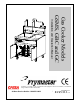
Gas Cooker Models GSMS, GBC and GC Installation and Operation Manual Frymaster, a member of the Commercial Food Equipment Service Association, recommends using CFESA Certified Technicians.
DANGER IMPROPER INSTALLATION, ADJUSTMENT, ALTERATION, SERVICE, OR MAINTENANCE CAN CAUSE PROPERTY DAMAGE, INJURY, OR DEATH. READ THE INSTALLATION, OPERATING, AND SERVICE INSTRUCTIONS THOROUGHLY BEFORE INSTALLING OR SERVICING THIS EQUIPMENT. DANGER FOR YOUR SAFETY, DO NOT STORE OR USE GASOLINE OR OTHER FLAMMABLE LIQUIDS OR VAPORS IN THE VICINITY OF THIS OR ANY OTHER APPLIANCE. DANGER POST IN A PROMINENT LOCATION THE INSTRUCTIONS TO BE FOLLOWED IN THE EVENT THE USER SMELLS GAS.
GAS COOKERS GSMS, GBC AND GC INSTALLATION AND OPERATION MANUAL TABLE OF CONTENTS CHAPTER 1: General Information 1.1 Applicability and Validity..................................................................................................1-1 1.2 Parts Ordering and Service Information ............................................................................1-1 1.3 Safety Information .............................................................................................................1-2 1.
GAS COOKERS GSMS, GBC, AND GC INSTALLATION AND OPERATION MANUAL CHAPTER 1: GENERAL INFORMATION RETAIN AND STORE THIS MANUAL IN A SAFE PLACE FOR FUTURE USE 1.1 Applicability and Validity The GSMS/GBC/GC model family has been approved by the European Union for sale and installation in the following EU countries AT, BE, DE, DK, ES, FI, FR, GB, IE, IT, LU, NL, NO, PT, AND SE.
In addition to the model number, serial number, and type of gas, please be prepared to describe the nature of the problem and have ready any other information that you think may be helpful in solving your problem. 1.3 Safety Information Before attempting to operate your unit, read the instructions in this manual thoroughly. Throughout this manual, you will find notations enclosed in double-bordered boxes similar to the one below.
delivers 80,000 BTUs (23.4 kW – 84.4, megajoules) to cook 10 pounds (4.5kg) of dry pasta per bulk basket. The cooker can also be used to reheat up to 12 10-ounce (0.28kg) packages of pre-cooked food at a time. The cookpot measures 18 x 24 x 8 inches (457 x 610 x 203 mm) and holds 2.7 gallons (48-liters) of water. Model Comparison: GSMS: The “Gas Spaghetti Magic System” consists of a gas cooker and rinse tank combination.
QUALIFIED SERVICE PERSONNEL Qualified service personnel are those who are familiar with Frymaster equipment and who have been authorized by Frymaster Corporation to perform service on Frymaster equipment. All authorized service personnel are required to be equipped with a complete set of service and parts manuals, and to stock a minimum amount of parts for Frymaster equipment. A list of Factory Authorized Service Centers (FASC) was included with the cooker when shipped from the factory.
GAS COOKERS GSMS, GBC, AND GC INSTALLATION AND OPERATION MANUAL CHAPTER 2: INSTALLATION INSTRUCTIONS 2.1 General Installation Requirements Qualified, licensed, and/or authorized installation or service personnel, as defined in Section 1.7 of this manual, should perform all installation and service on Frymaster equipment. Conversion of this appliance from one type of gas to another should only be performed by qualified, licensed, and/or authorized installation or service personnel as defined in Section 1.
installed so that products of combustion are removed efficiently, and that the kitchen ventilation system does not produce drafts that interfere with proper burner operation. The cooker flue opening must not be placed close to the intake of the exhaust fan, and the cooker must never have its flue extended in a “chimney” fashion. An extended flue will change the combustion characteristics of the cooker, causing longer recovery time. It also frequently causes delayed ignition.
with all local codes. In CANADA, installation must conform to Standard CAN/CGA-B149.1 or CAN/CGA-B149.2, Installation Codes for Gas Burning Appliances and Equipment. In addition, installation must comply with all local codes. InAUSTRALIA, this appliance must be installed by an authorized person in accordance with these instructions, local gas and electrical regulations, and the requirements of AA601, Installation Requirements for Gas Burning Appliances.
2.3 Pre-Connection Preparations DANGER Do not connect cooker to gas supply before completing each step in this section. After the cooker has been positioned under the exhaust hood, ensure the following has been accomplished: 1. Adequate means must be provided to limit the movement of cookers without depending upon the gas line connections. If a flexible gas hose is used, a restraining cable must be connected at all times when the cooker is in use.
6. Connect the desired drain plumbing to the 1¼–inch drain valve. 7. Test the cooker electrical system: a. Plug the cooker electrical cord into a grounded electrical receptacle of appropriate voltage. (Check the rating plate on the cooker door to determine the proper voltage). b. Place the power switch in the ON position and verify that the display indicates –LO. c. Place the cooker power switch in the OFF position. Verify that the display is blank. 8.
2.4 Connection to the Gas Line The GSMS/GBC/GC family of gas cookers has been approved for use with natural and propane (LP) gas. The cookers in this family have also received the mark for the countries and gas categories indicated in the accompanying table. CE Standard The nominal heat input (Qn) is 21kW except for AT, DE, LU and for category 3B/P under 50 mbar, which is 23kW.
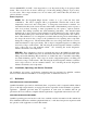
The size of the gas line used for installation is very important. If the line is too small, the gas pressure at the burner manifold will be low. This may cause slow recovery and delayed ignition. Frymaster recommends the incoming gas supply line be a minimum of 1 ½” (38mm) in diameter. Refer to the chart below for the minimum sizes of connection piping.
4. It is recommended that the burner gas pressure be checked at this time by the local gas company or an authorized service agent. Refer to “Check Burner Pressure” in Chapter 4 of this manual for the proper procedure. The accompanying tables list the burner gas pressures for the various gas types that can be used with this equipment.
CE Gas Conversion Instructions 1. Between G20- and G25- type Natural Gas, adjust the gas pressure at the gas valve regulator. (Refer to the CE Standard for Burner Gas Pressure Table on Page 2-7.) Do not change the orifices. 2. Between a 2nd family (G20 or G25) and a 3rd family gas (G31 Propane): a. Change the orifices. b. Change the ignitors. c. Adjust the incoming gas pressure for the new gas. (Refer to the CE Standard for Incoming Gas Pressure table on Page 2-5). d.
GAS COOKERS GSMS, GBC, AND GC INSTALLATION AND OPERATION MANUAL CHAPTER 3: OPERATING INSTRUCTIONS 1 10 2 1 2 3 4 5 3.1 3 4 Numeric Keypad Boil Mode Indicator Boil Mode Switch Power Switch LED Display 6 5 6 7 8 9 10 7 8 9 Skim Switch Timer Start Switch Simmer Mode Switch Simmer Mode Indicator Trouble Light Introduction The Spaghetti Magic Controller allows the operator to specify a cook time in minutes and seconds, then initiate a cooking cycle.
LOW WATER SENSING automatically closes the gas valve (thereby extinguishing the burner flame) if the water in the cookpot drops too low. When the water level in the cookpot is below the low-water sensor, such as when draining and cleaning the cookpot, the controller display will readLO.
2. On Non-CE units, turn the gas valve knob to the ON position (see illustration at right.) NOTE: CE gas valves do not have an ON/OFF knob. These valves will activate automatically when the controller power switch is placed in the ON position and the lower water level sensor is covered with water. The burners should light for several seconds and then go out. A few seconds later they should light again.
3.2.3 Boiling Out the Cookpot To ensure that the cooker is free of contamination from manufacture, shipping, or handling during installation, the cookpot must be boiled out before first use. 1. Close the drain valve and fill the cookpot with a mixture of cold water and 1 cup of detergent. 2. Place the unit into operation (see Section 3.2.1). 3. Press the Simmer Mode switch and allow the solution to simmer for at least 1 hour. 4.
GAS COOKERS GSMS, GBC, AND GC INSTALLATION AND OPERATION MANUAL CHAPTER 4: PREVENTIVE MAINTENANCE 4.1 Daily Preventive Maintenance It is normal for a coating of starch to form on the sensors and temperature probes during operation. If the coating is allowed to build-up, it will adversely affect the operation of the equipment. The preventive maintenance routines below should be performed at least daily to keep your equipment functioning at peak efficiency.
4.2 Cleaning the Gas Valve Vent Tube This procedure should be performed at least once every 90 days. NOTE: This procedure is not required for cookers configured for export to CE countries. The gas valves on CE units are not equipped with vent tubes. 1. Set the power switch and the gas valve to the OFF position. 2. Carefully unscrew the vent tube from the gas valve. NOTE: The vent tube may be straightened for ease in removal. 3. Pass a piece of ordinary binding wire (.
4. Wrap the motor with plastic wrap to prevent water from entering it. Spray degreaser or detergent on the blower wheel and the blower housing. Allow it to soak for five minutes. Rinse the wheel and housing with hot tap water, then dry with a clean cloth. Wrap the motor and wires with plastic wrap or a plastic bag. BLOWER HOUSING BLOWER WHEEL 5. Remove the plastic wrap from the blower motor assembly. Reassemble the blower motor assembly and blower housing.
TYPICAL NON-CE BLOWER ASSEMBLY 4.4 TYPICAL CE BLOWER ASSEMBLY Adjusting the Burner Gas Pressure DANGER Frymaster recommends that ONLY qualified service personnel perform this task. 1. On Non-CE cookers, ensure that the gas valve knob is in the OFF position. 2. Remove the pressure tap plug from the gas valve assembly. Pressure Tap Plug Typical Non-CE Valve Assembly Typical CE Valve Assembly 3. Insert the fitting for a gas pressure-measuring device into the pressure tap hole 4.
CE Standard for Burner Gas Pressure Gas Pressure Natural Lacq 7 mbar (G20) under 20 mbar Natural Gronique* 12 mbar (G25) under 25 mbar Propane 22,2 mbar (G31) under 37 mbar * Belgian G25 = 7,0 mbar 6. Non-CE Standard for Burner Gas Pressure Gas Pressure 3.5" WC Natural 0.87 kPa 8.718 mbar 8.25" WC Propane 2.05 kPa 20.55 mbar To adjust the burner gas pressure, remove the cap from the gas valve regulator and use a flat-tipped screwdriver to adjust the regulator to obtain the correct pressure.
determine which version of the controller you have, turn the controller off by pressing the power switch. The display will go blank. Press the Simmer Mode (right thermometer icon) switch. If Code appears in the display, the setpoint is changed via programming; if not, skip to Manual Adjustment on the next page. 1. Press 1, 6, 5, 0 to enter the programming mode. The currently programmed simmer setpoint will be displayed.
GAS COOKERS GSMS, GBC, AND GC INSTALLATION AND OPERATION MANUAL CHAPTER 5: OPERATOR TROUBLESHOOTING 5.1 Introduction This chapter provides a reference guide to the more common problems that may occur during the operation of this equipment. The troubleshooting guides in this chapter are intended to help you correct, or at least accurately diagnose, problems with the equipment. Although the chapter covers the most common problems reported, you may very well encounter a problem not covered.
5.2 Operator Troubleshooting Guides Problem Probable Causes A. Ignition module lockout (the burners failed to light within 4 seconds). BURNERS DO NOT LIGHT (Main gas supply B. valve verified to be open, the gas valve in Non-CE units is verified to be ON, and power switch is C. verified to be ON.) D. A. ON UNIT WITH AUTOFILL, COOKPOT DID B. NOT FILL WHEN UNIT WAS TURNED ON (Water supply to unit verified to be ON.) C. Corrective Action A. Turn the controller OFF.
Problem ON UNIT WITH AUTOFILL, WATER DID NOT SHUT OFF WHEN COOKPOT WAS FULL AUTOSKIM DOES NOT WORK (AUTOFILL functions correctly.) WATER WILL NOT BOIL (Cookpot verified to be full of water with Boil Mode selected, i.e., left indicator is lit and burners are lit.) WATER BOILS IN SIMMER MODE Probable Causes Corrective Action A. Dirty water level sensors. (If the A.
Problem Probable Causes A. Controller out of adjustment. B. Failed controller. WATER TEMPERATURE IS TOO LOW IN SIMMER MODE BASKET LIFT MOVEMENT IS JERKY OR NOISY Corrective Action A. Adjust controller in accordance with procedure in Chapter 4. B. Order replacement controller from FASC or distributor. Test: If another controller known to be working is available, substitute the working controller for the suspect controller. If the unit begins to fill, the controller has failed. C.
5.
5.4 Replacing the Controller 1. Disconnect the cooker from the electrical supply. 2. Remove the two screws in the upper corners of the control panel and swing the panel open from the top, allowing it to rest on its hinge tabs. 3. Disconnect the wiring harness from the back of the controller. 4. Disconnect the ground wire from the controller. Remove the control panel by lifting it from the hinge slots in the frame. 5.
THIS PAGE INTENTIONALLY LEFT BLANK
Frymaster, L.L.C.