
User's Manual


11
To start the bootloader application the master device command the RFID reader board to switch to bootloader program using
modbus interface (P-BUS). When the firmware update is done, the master device commands the RFID reader board to start
execution of the main application.
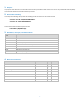
Each frame has address, function code, packet data and CRC16. The function codes of boot loader are as follow:
• #define MODBUS_CMD_START_APP 0x55 /* exit boot loader and start main application */
• #define MODBUS_CMD_START_BOOT 0x56 /* exit main application and start boot loader */
• #define MODBUS_CMD_WRITE_FLASH 0x57 /* write firmware data to flash memory */
• #define MODBUS_CMD_READ_OK 0x58 /* response from slave board when command is ok */
For the write flash command, the first 4 bytes are the address (in little-endian format) in flash memory and the next 128 bytes are
the data to write (128 bytes = 32 program memory words). For the other commands the packet data is not used and should filled
with 0's.
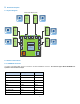
7.2 Microcontroller Configuration
The microcontroller is configured to reset to auxiliary flash program memory where the bootloader is programmed to auxiliary flash
memory.
The oscillator is configured to use external clock source where the microcontroller is clocked externally from the signal SYS_CLOCK
from the RFID transceiver. The PLL is enabled and configured to provide 120 MHz Fosc. The CPU clock (instruction execution speed)
is 60 MHz.
The watchdog timer is always enabled (by hardware) and the post-scale and pre-scale are configured so that the WDT period is
4.096 second.
The microcontroller In-Circuit Serial Programming is configured to communicate on PGEC1 and PGED1. The JTAG is disabled.
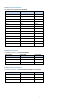
7.3 RFID Transceiver Configuration
The RFID transceiver is configured to provide 3.39 MHz system clock for MCU. The modulation Type and depth is set to OOK (100%).
The RFID Transceiver regulators configuration is set automatic setting - VDD_RF = 4.9 V, VDD_A = 3.4 V, VDD_X = 3.4 V.
The RFID is configured to operate in 5V V
IN
voltage range and to operate in RFID mode. The RFID is configured to use ISO15693
protocol.
In RFID Reader software, the RFID transceiver is controlled by ReaderController active object. The software is reading the first 2
blocks in user data area from the RFID tag using ISO15693 READ SINGLE BLOCK command.
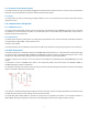
7.4 RFID Zone Scanning
The RFID zone scanning is done by selecting the analog input to read by controlling the output status of MUX_SEL0 to MUX_SEL3
signals and then trigger the ReaderController to start read the tag on the selected channel. The RFID zone scanning is controlled by
SystemController active object. The system controller reads channels sequentially and each channel is read twice, the first time
block 0 is read and the second time block 1 is read from user data memory in the RFID tag.