
User's Manual


8
6. Hardware Description
6.1 Power
6.1.1 Input Power
The RFID reader board derives all power from the 12VDC(+/-10%) and 5VDC(+10%/-5%) as defined per the MODBUS connector. The
reader generates 3V3 from the 5VDC rail using an MCP1700T LDO rated at 250mA. The 5V2 voltage is generated from the 12VDC rail
using an AZ1117LDO rated at 800mA.
6.1.2 RF Output Power
When configured for 5-V operation (see section 6.6), the RF amplifier voltage can be set from 4.3V to 5V in 100mV steps via software.
In 3-V operation, the RF amplifier can be set from 2.7V to 3.4 in 100mV steps. The typical output power at maximum setting is
17dBm@3-V operation and 23dBm@5-V operation.
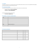
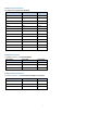
6.2 ID Select Jumper
The MODBUS ID of the reader board can be set using a standard 100 mil jumper on J13 per the following table:
MODBUS ID
JUMPER POSITION
RFID_ ID1
Jumper across J13-1 and J13-2
RFID_ ID2
Jumper across J13-2 and J13-3
RFID_ ID3
No jumper installed
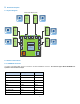
6.3 Indicators
The reader board provides an LED for each of the power rails; 5V2_VDC(GREEN), 3V3_VDC(GREEN).
The reader board provides a BLUE LED for each of the RF antenna zones 1 through 12 (as shown in appendix B). Each LED will illuminate
whenever a valid tag is detected on an attached RFID antenna.
The reader board provides a GREEN LED to indicate the status of the microcontroller as well as an ORANGE LED to indicate the
communication on the MODBUS.
6.4 Microcontroller
6.4.1 Microcontroller
The RFID reader board uses Microchip PN PIC24EP512GU810-I/PF in a 100 pin TQFP package. The micro has the following standard
features:
• 512kB Program Flash Memory
• 52kB RAM
• 4 Channel UART
• 2 Channel SPI
• 83 General Purpose I/O pins
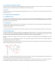
6.4.2 Clock
The microcontroller is clocked externally from the signal SYS_CLOCK from the RFID transceiver.