CAP600 REV B JUNE 2012 CA/CT Series TWO STAGE RECIPROCATING AIR COMPRESSORS Installation and Operations Manual
CA / CT SERIES Page 1 of 30 ______________________ Model CAP600 REV B June 2012 _____________________ Serial # Please have your unit’s model and serial number ready when calling for service. The model # is found on the tank decal and the serial number is located on the compressor nameplate. For Customer Service, Technical Service, or to order replacement parts, please contact your local distributor. FS Curtis, Inc. 1905 Kienlen Avenue, St.
CA / CT SERIES Page 2 of 30 CAP600 REV B June 2012 Table of Contents Read Me First Section 1 Safety Precautions ............................................................................................................ 3-4 System Diagram ............................................................................................................... 5-6 Installation Section 2 Receiving ...................................................................................................................
CA / CT SERIES Page 3 of 30 CAP600 REV B June 2012 READ ME FIRST Safety Precautions The owner, lessor or operator of any compressor unit manufactured by FS Curtis, Inc. is hereby warned that failure to observe all safety precautions may result in serious injury of personnel and/or damage to property. FS Curtis, Inc.
CA / CT SERIES Page 4 of 30 CAP600 REV B June 2012 • Turn off and lockout/tagout the main power disconnect switch before attempting to work or perform any maintenance. • Do not attempt to service any part of this unit while it is running. • Ensure that service personnel are properly grounded before attempting to service any part of the electrical system. • Do not operate the unit with any of its safety guards, shields or screens removed.
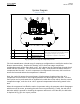
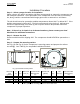
CA / CT SERIES Page 5 of 30 CAP600 REV B June 2012 System Diagram Simplex Units 1 2 3 4 5 6 1 Air Intake 4 Magnetic Starter 2 Air Compressor 5 Pressure Switch 3 Intercooler 6 Vibration Pads with hardware mounts Exact orientation of system components may vary. Please see your model's general arrangement diagram for a precise configuration of system components. Fig. (1) Simplex, two stage air compressor process.
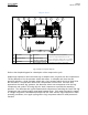
CA / CT SERIES Page 6 of 30 CAP600 REV B June 2012 Duplex Units 1 2 3 5 4 5 1 2 3 6 1 Air Intake 4 2 Air Compressor 5 3 Intercooler 6 Exact orientation of your system's components may be different from the Pressure Switch layout in the figure. Please see your model's Vibration Isolator pads general arrangement diagram for a precise with hardware mounts configuration of system components. Alternator Fig. (2) Duplex unit system diagram.
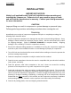
CA / CT SERIES Page 7 of 30 CAP600 REV B June 2012 INSTALLATION IMPORTANT NOTICE Abide by all applicable state, local and regulations when mounting and installing the compressor. Failure to do so may result in injury or death and will void the manufacturer’s warranty. Contact your local government for more information. CAUTION! Improper lifting can result in component or system damage or personal injury. Follow good shop practices and safety procedures when moving the unit.
CA / CT SERIES Page 8 of 30 CAP600 REV B June 2012 FREIGHT DAMAGE The transportation industry has adopted a modification with regard to the handling of obvious and concealed damage claims. Therefore, it is extremely important that you examine every carton and crate as soon as you receive it. If there is any obvious damage to the shipping container, have the delivering carrier sign the freights bill, noting the apparent damage, and request a damage report.
CA / CT SERIES Page 9 of 30 CAP600 REV B June 2012 Installation Procedure Step 1 – Select a proper location for installation Select a clean, dry, well lit area with a rigid floor strong enough to support the compressor and with adequate ventilation. Avoid placement of the compressor in an area that is excessively hot, dusty, humid or contaminated with foreign gases such as ammonia or acid fumes. The unit should never be operated at ambient temperatures above 104°F or below 32°F.
CA / CT SERIES Page 10 of 30 • • • CAP600 REV B June 2012 Acceptable Mounting Concrete Anchor Bolts Threaded Rod or Floor Stud Steel flooring or supports (provided unit is bolted down and isolator pads are used) • • • Unacceptable Mounting Skid Mounted Unanchored Bare Floor (no vibration pads) Table (2) Compressor mounting methods If you wish to utilize an installation method other than the approved methods described in Table (2), please contact your local distributor.
CA / CT SERIES Page 11 of 30 CAP600 REV B June 2012 Recommended Installation – Use concrete anchor bolt 2 1 4 3 6 5 8 7 Fig.
CA / CT SERIES Page 12 of 30 CAP600 REV B June 2012 Step 5 – Tighten the fasteners Incrementally tighten the mounting bolts evenly in a cross pattern. If necessary, after start up, continue incrementally tightening the mounting bolts in a crossing pattern until vibrations have been reduced to an acceptable level. After vibrations have been minimized, loosen ONE mounting bolt.
CA / CT SERIES Page 13 of 30 CAP600 REV B June 2012 Post Installation Checklist WARNING! Failure to perform the post installation checklist may result in mechanical failure, property damage, serious injury or even death. Steps 1 through 9 should be performed prior to connecting the unit to a power source. If any condition on the checklist is not satisfied, make the necessary adjustments or corrections before starting the compressor. 1.
CA / CT SERIES Page 14 of 30 CAP600 REV B June 2012 Electrical Requirements The electrical installation of this unit should only be performed by a qualified electrician with knowledge of the National Electrical Code (N.E.C.), O.S.H.A. code and/or any local or state codes having precedence. All FS Curtis compressors come with a factory installed, pre-wired starter, if you wish to provide your own starter, please contact your local distributor for more information.
CA / CT SERIES Page 15 of 30 CAP600 REV B June 2012 Wiring Diagrams: Simplex Single Phase and 3 Phase TURN OFF / TAGOUT POWER BEFORE SERVICING 1 2 3 1 2 3 4 5 L1 L2 L3 Overload relay Reset switch 4 5 Fig (7) Simplex Starter MS1 L1 L2 L3 OL T1 T2 T3 Motor Jumper T2 to L3 Power Supply to L1 and L2 M Pressure Switch A1 A2 OL 95 96 Fig (8) Single Phase wiring diagram MS1 L1 L2 L3 OL T1 T2 T3 Motor Power Supply to L1, L2, and L3 M Pressure A1 A2 Switch OL 95 96 Fig (9) Three phase wir
CA / CT SERIES Page 16 of 30 CAP600 REV B June 2012 Wiring Diagrams: Duplex Dual Source Alternator TURN OFF / TAGOUT POWER BEFORE SERVICING 3 2 1 3 2 1 1 2 3 L1 L2 L3 Fig (10) Duplex dual source alternator panel. NOTE: Unit wiring diagram is located on the inside front cover of the alternator panel. If, over time, the diagram becomes illegible, please contact your local distributor.
CA / CT SERIES Page 17 of 30 CAP600 REV B June 2012 Start Up Pre Start Checklist WARNING! Do not proceed until the PRE-STARTING CHECKLIST and sub-section has been read and is thoroughly understood. 1. Check oil level in crankcase for proper level. 2. Drain liquid from the air receiver and moisture trap (if so equipped). 3. Check system pressure. Do not operate the compressor in excess of the A.S.M.E. pressure vessel rating for the receiver or the service rating of the compressor, whichever is lower. 4.
CA / CT SERIES Page 18 of 30 CAP600 REV B June 2012 For the first weeks, the compressor needs time to “break in.” The belt requires time to stretch and fit into the surface of the pulleys. The piston rings need time to seat themselves into the cylinder walls, and bearings need to wear into place. For the first 100 hours or so, the compressor will consume higher than normal amounts of oil until the break in process is complete.
CA / CT SERIES Page 19 of 30 CAP600 REV B June 2012 Maintenance Shut Down Procedure The following procedures should be followed when stopping the compressor for maintenance or service. WARNING! Never assume a compressor is safe to work on just because it is not operating. It could start at any time. 1. Per O.S.H.A. regulation 1910.147; The Control of Hazardous Energy Source (Lockout/Tagout); disconnect and lockout the main power source.
CA / CT SERIES Page 20 of 30 CAP600 REV B June 2012 Maintenance Schedule To assure maximum performance and service life of your compressor, a routine maintenance schedule should be developed. A sample schedule has been included to help you develop a maintenance schedule designed for your particular application. Time frames may need to be shortened in harsher environments or during periods of extremely heavy use.
CA / CT SERIES Page 21 of 30 CAP600 REV B June 2012 Oil OIL RECOMMENDATION Use Genuine CURTIS-LUBEPLUS Lubricants. Specially formulated for Curtis Reciprocating Air Compressors. Non-Detergent type with anti-foam, anti-rust and oxidation inhibitors. In areas with very hot ambient air temperatures, FS Curtis recommends using ISO100 RC1000A CURTIS-LUBEPLUS. 1. For proper lubrication the compressor shall not be operated below the minimum or above the maximum R.P.M. recommended for the various models. 2.
CA / CT SERIES Page 22 of 30 CAP600 REV B June 2012 Bolt Torques Challenge Air and CT Compressors E50 E57 E71 E15 Size Torque (CM-FT) Size Torque (CM-FT) Size Torque (CM-FT) Size Torque (CM-FT) Head Bolts M10-1.5 300-21.7 M10-1.5 320-23.1 M10-1.5 320-23.1 M10-1.5 320-23.1 Cylinder Case M10-1.5 280-20.35 M10-1.5 280-20.25 M10-1.5 280-20.25 M10-1.75 350-25.3 Rod Bolts M8-1.5 280-20.25 M8-1.25 280-20.25 M8-1.5 300-21.7 M10-1.5 300-23.1 Front Cover M8-1.5 280-20.
CA / CT SERIES Page 23 of 30 CAP600 REV B June 2012 BELT TENSION CAUTION: Over tightening the v-belt(s) will result in overloading of the motor, and/or belt and pulley failure. A loose belt will result in an unstable speed, premature belt wear, “throwing” belts and a high amp draw. To change tension, turn the adjusting bolt at the end of the base, shown in figure 13. Retighten motor hold-down bolts. Grease both the motor and compressor pulleys once a year with lithium ball bearing grease.
CA / CT SERIES Page 24 of 30 CAP600 REV B June 2012 Model HP Gage Deflection Average Tension 555VT6 5 1/4" 13lb 11lb 14lb 555VT8 5 1/4" 10lb 9lb 12lb 775VT8 7.5 1/4" 10lb 9lb 12lb 1075HT12 10 1/4" 8lb 7lb 10lb CT Gas 13-14 3/8" 20lb 18lb 23lb Minimum Maximum Table (8) CT Belt Tensioning Guide Compressor Pulley DIRECTION OF APPLIED FORCE Motor Pulley 3. Fig (15) Proper belt tensioning 4.
CA / CT SERIES Page 25 of 30 CAP600 REV B June 2012 Maintenance Parts and Rebuild Kits To order replacement parts for routine maintenance, please contact your local distributor.
CA / CT SERIES Page 26 of 30 CAP600 REV B June 2012 Troubleshooting Problem 1 Unit won’t start Cause Remedy • Power not on • Check breaker and / or disconnect • Fuse blown • Replace the fuse or disconnect • Low voltage supplied • Contact distributor • Worn pressure switch contacts • Replace • Starter overload tripped • Reset starter overload • Broken / loose electrical • Check electrical connections connections 2 3 4 Flywheel / motor rotating clockwise Flywheel /motor rotating slowly
CA / CT SERIES Page 27 of 30 CAP600 REV B June 2012 Problem Cause • Manual drain not fully closed Remedy • Close the drain cock (standard model) • Automatic drain not fully closed (if • Clean or replace automatic drain applicable) 7 8 Low discharge pressure Excessive belt wear • Clogged air filter / intake • Replace the filter • Leaks in air distribution system • Check fittings, bushings and connections for leaks • Clogged air distribution system • Clean air distribution system • Worn out
CA / CT SERIES Page 28 of 30 CAP600 REV B June 2012 Maintenance Checklist NOTE: Please keep a record of changes and have this list available when calling technical service.
CA / CT SERIES Page 29 of 30 CAP600 REV B June 2012 Maintenance Checklist NOTE: Please keep a record of changes and have this list available when calling technical service.
CA / CT SERIES Page 30 of 30 CAP600 REV B June 2012 Maintenance Checklist NOTE: Please keep a record of changes and have this list available when calling technical service.
FS Curtis 1905 Kienlen Ave., St. Louis, MO 63133 (800) 925-5431 FAX (314) 381-1439 EMAIL: info@curtistoledo.com Website: www.fscurtis.