
Product Manual

CA / CT SERIES
CAP600
Page
12
of
30
REV B June 2012
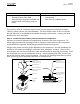
Step 5 – Tighten the fasteners
Incrementally tighten the mounting bolts evenly in a cross pattern. If necessary, after start up,
continue incrementally tightening the mounting bolts in a crossing pattern until vibrations have
been reduced to an acceptable level. After vibrations have been minimized, loosen ONE
mounting bolt. The unit expands and contracts with changes in temperature, leaving ONE bolt
loosened will allow for thermal expansion of the unit, reducing thermal stresses and vibrations
on the tank. If after loosening one bolt the vibrations get worse, retighten bolt and select a
different unit. Excessive vibrations can damage equipment.
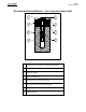
Step 6 – Install piping network
Run a clean pipe to the tank discharge opening, bushing up or down as necessary with clean
bushings and fittings. Note that the more bushings and fittings placed in the air distribution
system, the greater the opportunity for air leaks and breaks. FS Curtis recommends the
installation of drip legs in the distribution line.
Always install a safety relief valve in the distribution line between the compressor unit and in-
line shutoff valves. If more than one compressor pumps into a common system, a check valve
in the distribution line of each compressor unit is recommended to prevent moisture from
entering the cylinder head(s) when one compressor is idle. A globe or gate valve (WOG rated)
installed in the discharge line will allow compressor isolation from plant air system for
compressor maintenance. (Note: A safety relief valve should be located between the
compressor and the globe/gate valve.)
Step 7 – Install Compressor Intake (IF APPLICABLE)
If the compressor intake is to be located away from the unit, please use the following
instructions to ensure safe and efficient operation.
Run a clean pipe to the compressor suction opening, bushing up or down as necessary with
clean bushings and fittings. Note that the more bushings and fittings placed in the intake line,
the greater opportunity for air leaks and breaks. If the run is over 10 feet in length, use a larger
pipe diameter to avoid excessive pressure drops. When installing the pipes, please pitch the
piping down and slightly away from the intake, to ensure that debris and condensation drains
away from the compressor.
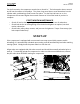
MOUNTING MOBILE UNITS
Gas engine driven compressors mounted to truck beds should be fastened to the truck bed in
such a way so as not to create any stress to the air receiver tank. Truck beds,
characteristically, have a tendency to flex and could cause damage to the receiver tank if the
tank is fastened directly to the truck bed. It is the User’s responsibility to provide an adequate
means of fastening the unit in these applications.