7428141 AUGUST 2012 CF SERIES COMPRESSED AIR FILTERS OPERATOR MANUAL CF12 CF24 CF36 CF48 CF16 CF28 CF40 CF20 CF32 CF44
Model Number Configuration CF (1) (1) Filter Grade - (2) - (2) Housing 11 - Mechanical Separator 9 - Separator/Filter 7 - Air Line Filter 6 - Dry Desiccant After-filter 5 - High Efficiency Oil Removal Filter 3 - Maximum Efficiency Oil Removal Filter 1 - Oil Vapor Removal Filter Number (3) - (4) (3) Connection Sizes Capacity scfm (m3/hr) @ 100 psig (7 kfg/cm2) 12 16 20 20 (35) 35 (60) 60 (105) 3- 3/8" NPTF or 4- 1/2" NPTF 3B- 3/8" BSP or 4B- 1/2" BSP 24 28 100 (170) 170 (290) 6- 3/4" NPT
General Safety Information 3. Flammable gases 1. Pressurized devices While the materials of construction are compatible with many flammable gases, the following application limitations must be considered: • Do not exceed maximum operating pressure indicated on serial number tag. • Make certain filter is fully depressurized before servicing. • Housing materials are slightly porous. The product must be used in a well ventilated area in the absence of sparks or ignition sources.
C. Piping 1. Before installing, blow out pipe line to remove scale and other foreign matter. Wall Mounting Bracket Top Cap Figure 1.3 Figure 1.1 2. This unit has DRYSEAL pipe threads; use pipe compound or tape sparingly to male threads only. 3. Mounting (Grades 11, 9, 7, 5, 3) - mount so that inlet and outlet connections are horizontal (filter bowl vertical) to ensure proper liquid drainage. 4. Flow Direction - install so that the air flow is in the direction of arrows on the filter head.
D. Drain provisions 2. 1. Internal Automatic Drains - Drain line The bottom of internal automatic drains are provided with 1/8" (inside threads) for connection of a drain line if desired. 2. External Auto Drains - External auto drains may be added as follows: Models 12 through 28 - remove internal drain and install adapter (available from factory). Adapter outlet connection is 1/8" (inside threads). Discharge is at system pressure; anchor drain line.
3.0 Maintenance 5. A. When to Replace Filter Element NOTE: Grades 7, 6, 5, 3, 1, - complete element is replaced; Grade 9 - unless separator core is damaged outer sleeve only is replaced. 1. Grade 6 (dry desiccant after-filter) Initial drop: 1 psi (0.07 kgf/cm2). Pressure drop increases as element loads with solid particles. Replace when pressure drop reaches 6 psi (0.42 kgf/cm2) (indicator in yellow area) or annually, whichever occurs first. Reference page 5, Figure 3.2 for gauge scale detail. 2.
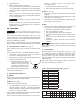
8.15 (207) 6.40 (163) 3.00 (76) 4.14 (1.88) "B" in. (mm) "C" in. (mm) "D" in. (mm) Weight lb. (kg) Aluminum Aluminum Isoplast Bowl Material Liquid Level Indicator Material "D" CLEARANCE FOR SERVICING OUTLET Sizes CF(Grade) 12, 16, 20 INLET "A" "C" "B" 1" (26mm) INLET "D" Sizes CF(Grade) 24, 28 CLEARANCE FOR SERVICING OUTLET "C" "B" Figure 3.2 2.3" (58.4mm) INLET "D" CLEARANCE FOR SERVICING OUTLET "C" "B" HEX WRENCH 3.00 ACROSS FLATS 2.3" (58.
WARRANTY The manufacturer warrants the product manufactured by it, when properly installed, operated, applied, and maintained in accordance with procedures and recommendations outlined in manufacturer’s instruction manuals, to be free from defects in material and workmanship for a period of one (1) year from date shipment to the buyer by the manufacturer or manufacturer’s authorized distributor provided such defect is discovered and brought to the manufacturer’s attention within the aforesaid warranty perio