
Datasheet

6
Copyright © 2012 Future Technology Devices International Limited
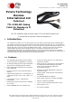
TTL-232R-RPi
Version 1.0
Document Reference No.: FT_000722 Clearance No.: FTDI# 296
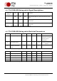
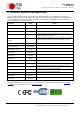
4.2 TTL-232R-RPi Debug cable Signal Descriptions
Header Pin
Number
Name
Type
Colour
Description
1
GND
GND
Black
Device ground supply pin. Connect to ground pin on RPi
board
2
TXD
Output
Orange
Transmit Asynchronous Data output. Connect to RXD input
on RPi board
3
RXD
Input
Yellow
Receive Asynchronous Data input. Connect to TXD output
on RPi board
Table 4-1 – TTL-232R-RPi Debug cable Signal Descriptions
4.3 TTL-232R-RPi Debug cable Electrical Parameters
Parameter
Description
Minimum
Typical
Maximum
Units
Conditions
VCC
Power Input Voltage
4.25
5.0
5.25
V
Dependant on the USB
port that the TTL-232R-
RPi Debug cable is
connected to
I
O
Power Input Current
-
-
15
mA
Less than 70uA during
suspend.
T
Operating Temperature
Range
-40
-
+85
o
C
Table 4-2 – TTL-232R-RPi Debug cable Operating Parameters
Parameter
Description
Minimum
Typical
Maximum
Units
Conditions
Voh
Output Voltage High
2.2
2.8
3.2
V
I source = 3mA
Vol
Output Voltage Low
0.3
0.4
0.6
V
I sink = 8mA
Vin
Input Switching Threshold
1.0
1.2
1.5
V
Vhys
Input Switching Hysteresis
20
25
30
mV
Table 4-3 – TTL-232R- RPi Debug cable I/O Pin Characteristics