
Datasheet

7
Copyright © 2012 Future Technology Devices International Limited
TTL-232R-RPi
Version 1.0
Document Reference No.: FT_000722 Clearance No.: FTDI# 296
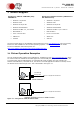
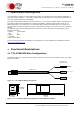
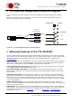
5 TTL-232R-RPi Debug cable connection diagram
The TTL-232R-RPi Debug cable should be connected to Raspberry Pi board according to the diagram
below.
Please note that TXD-orange wire should be connected to RX pin on RPi board and RXD-yellow wire
should be connected to TX pin on RPi board.
top leftbottom left
0V (GND)
TX
RX
CABLE 1.0m
1
2
3
3x single pole
0.1in pitch header
BLACK
ORANGE
YELLOW
TX
RX
GND
Figure 5-1 – TTL-232R-RPi Debug cable, connection diagram
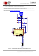
6 Advanced Features of the TTL-232R-RPi
The TTL-232R-RPi debug cable utilizes FTDI’s FT232RQ USB to serial IC device. This section summarises
the key features of the FT232RQ which apply to the TTL-232R-RPi debug cables. For further details, and a
full features and enhancements description consult the FT232R datasheet, this is available from
www.ftdichip.com.
Internal EEPROM. The internal EEPROM in each cable is used to store USB Vendor ID (VID), Product ID
(PID), device serial number, product description string and various other USB configuration descriptors.
Each cable is supplied with the internal EEPROM pre-programmed as described
Lower Operating and Suspend Current. The FT232R has a low 15mA operating supply current and a
very low USB suspend current of approximately 70μA.
Low USB Bandwidth Consumption. The USB interface of the FT232R, and therefore the TTL-232R
cables has been designed to use as little as possible of the total USB bandwidth available from the USB
host controller.
High Output Drive Option. The UART interface I/O pins on the TTL-232R-RPi Debug cable (RXD and
TXD) can be configured to use the FT232R’s high output drive option. This option allows the FT232R I/O
pins to drive up to three times the standard signal drive level. This allows multiple devices to be driven,
or devices that require greater signal drive strength to be interfaced to the cables. This option is enabled
in the internal EEPROM.
UART Pin Signal Inversion. The sense of UART signals can be individually inverted by configuring
options in the internal EEPROM. For example RXD (active high) can be changed to RXD# (active low) and
TXD can be changed to TXD#.
FTDIChip-ID™. The FT232R includes the new FTDIChip-ID™ security dongle feature. This FTDIChip-ID™
feature allows a unique number to be burnt into each cable during manufacture. This number cannot be
reprogrammed. An application note, AN232R-02, available from FTDI website (www.ftdichip.com)
describes this feature.