
Datasheet

8
Copyright © 2012 Future Technology Devices International Limited
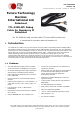
TTL-232R-RPi
Version 1.0
Document Reference No.: FT_000722 Clearance No.: FTDI# 296
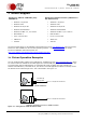
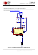
7 TTL-232R-RPi Circuit Schematic
The circuit schematic for the small internal electronic circuit board, utilising the FTDI FT232R, which is
encapsulated into the USB connector end of the cable, is shown in Figure 7-1.
Customised versions of these cables are also available. Users interested in customised versions of these
cables should contact FTDI sales (sales1@ftdichip.com).
RXD
TXD
GND
GNDGND
GND
GND GND
VCC
1
2
3
4
5
CN1
CN-USB
C1
10nF
FB1
600R/0.5A
C2
0.1uF
VCCIO
1
RXD
2
RI
3
GND
4
DSR
6
DCD
7
CTS
8
CBUS4
9
CBUS2
10
CBUS3
11
USBDP
14
USBDM
15
3V3OUT
16
GND
17
RESET#
18
VCC
19
GND
20
CBUS1
21
CBUS0
22
AGND
24
TEST
26
OSCI
27
OSCO
28
TXD
30
DTR
31
RTS
32
GND
33
U1
FT232RQ
C3
47pF
C4
47pF
C5
4.7uF
R1
100R
[Yellow]
[Orange]
GND
[Black]
Figure 7-1 – Circuit Schematic of PCB Used in the TTL 232R-RPi Debug cable