TSF 310 CI USER’S MANUAL
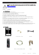
User’s manual · TSF 310 CI NOTE: This user’s guide is adapted to software version v.0.1.26 of TSF 310 CI dated 25/11/2011. For future software updates, you can download the user’s guide from the following website: http://www.ftemaximal.com/ Chapter 1. Installation. 1.1. Safety Measures 1.- Never place the device next to hot sources. 2.- Never undergo the device to temperatures that exceed its level of operation. 3.- Never expose the device to leakings nor spatterings. 4.
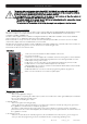
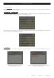
User’s manual · TSF 310 CI The models with a serial number higher than 075511441882 will be provided with a double DVB-T output that will allow distributing the channels of the tuned transponder in two consecutive multiplex. In order to configure the device we will have two selectable modules. The configuration of the input (transponder) is the same for both modules, all the other options of configuration are independent.
User’s manual · TSF 310 CI Stages of transmodulator TSF 310 CI Input Selection of a tuned satellite transponder Transmodulation Models with a serial number lower than a 075511441882 Models with a serial number higher than a 075511441882 The tuned channels of the transponder are modulated according to the DVB-T rules. If the transponder has encoded channels, in order to distribute them freely you have to install the PCMCIA + subscriber card in the Common Interface slot.
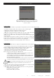
User’s manual · TSF 310 CI 1.4.2. Programming Below you will find the steps to follow in order to make the programming both from corresponding EVO and MINI field strength meter as well as from PRO 201. mediaMAX EVO / mediaMAX MINI In order to start programming the TSF 310 CI transmodulator, you will have to go to “Tools” option through the key 8 of your field strength meter and to select the “Transmodulator Prog.“ option. Then, it will proceed to recognize the module and to show the main menu.
User’s manual · TSF 310 CI If you have a module with a serial number higher than 075511441882 it will allow you to choose between two units with an only device connected to the programmer (Unit 1 or Unit 2.) 2. Device Status In the option “Device Status” are specified the main parameters of the module at this moment. - Front End: It indicates whether the module is hooked or without signal. - Input bit rate: Transfers of data in the satellite tuner input.
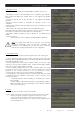
User’s manual · TSF 310 CI 4. Modulator Set Up This option allows configuring the DVB-T/DVB-H modulator of the device. - Bandwidth: Selection of the Bandwidth of the modulated signal: 8 MHz, 7 MHz, 6 MHz and 5MHz. The 5 MHz option is only supported by DVB-H standard. - FFT Mode: 8K, 4K and 2k. The 4k option is only supported by DVB-H standard. -Spectrum inversion: Activate or deactivate the spectrum reverse in the modulation.
User’s manual · TSF 310 CI - NM low Limit (dB): An event of error will be recorded when the value of Noise Margin is lower than the set value. - NM hight limit (dB): Once the event of error is recorded (Noise Margin < Limit Lower NM), this will be Noise Margin value that will have to be exceed so the module stops being in error. - Clear log all devices. It allows deleting the events report of all the interconnected modules.
User’s manual · TSF 310 CI 7. Program management - New program: This option allows creating a program with the current configuration of a module or group of modules. - Load program: It allows loading a previously created program on a module or group of modules. - Delete program: It allows deleting a program. - Device to process: - Current: The creation or loading of a program will be applied only in the module that is currently connected.
User’s manual · TSF 310 CI Adding services: 1. Select “Service to add” option 2. Select one of the transponder services you want to add. 3. Once you have chosen the service, select the “Add/Remove” button to include the service in the multiplex. Note: It is not recommended to exceed the 85% of the maximum capacity of the multiplex due to the possible variability of the bits rate of the inputs services.
User’s manual · TSF 310 CI - Bandwidth limitation: It allows selecting the % of the capacity of the output channel. - Auto service addition: - On: It selects the services automatically when an input carrier is tuned and when the list of selected services is empty. The receiver will have this state by default. - Always: It selects the services automatically every time a new input carrier is tuned. This state is only recommended to be used for making test in the module.
User’s manual · TSF 310 CI Next it is attached the identification table (NID/ONID) of the main satellites. You will be able to find more information in the law ETSI TR 101 162 v1.2.1. Satellite Hotbird 13ºE (Eutelsat 13ºE) Astra 19.2ºE Astra 23ºE Astra 28,2ºE Nilesat 7ºW Hispasat 30ºW Net ID 318 1 3-25 2 2048 33 Original Net ID 318 1 3-25 2 2048 33 Description Eutelsat 13ºE System Astra Satellite Network 19,2ºE Astra n (n=1-23) Astra Satellite Network 28,2ºE Nilesat 101 Hispasat Network 1 9.
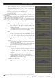
User’s manual · TSF 310 CI 1. Manual Inside the “manual” menu there are specified the different options for setting up the input, output and modulation parameters. Nota: If you have a module with a serial number higher than 075511441882 it will allow you to choose between two units with an only device connected to the programmer (Unit 1(Mux 0) or Unit 2 (Mux 1)). 1. This field shows the type of parameter that is selected at the moment. Options: Input Sat, Out Terr, Out TV. 2.
User’s manual · TSF 310 CI Note: The output useful bits rate will depend on the following parameters: Bandwidth, guard interval, FEC codification and modulation. In the Attachment I you will find all the information related to the resulting useful bit rate in each configuration. Output configuration ( TV output) In these options you can configure the output parameters of the terrestrial signal.
User’s manual · TSF 310 CI 3. Config In “Config” option the information concerning the transmodulator is given. TSF 310 CI LCN >Read file Delete file - Read log: It allows reading the registered events in the module. TSF 310 CI LCN >Read LOG file Delete LOG file 1. Select the option “Read LOG file” through Up/Down buttons. Press OK to continue TSF 310 CI TSF 310 CI N:00001 Status:03 07/02/11 09:05:02 Front-end lock OK to Show LOG 2. Press OK again to show the log file. 3. A new window will appear.
User’s manual · TSF 310 CI - (1) LCN: The LNC function allows assigning automatically a predetermined TSF 310 CI position to each one of the services of the multiplex. This function will allow the users who have a receiver with LNC support to make the ordination of channels LCN:00004 arte HD automatically. Select a channel through Left/Right buttons and introduce the position. Press the “OK” button and the cursor will be placed over the number.
User’s manual · TSF 310 CI 1.5. Accessories and example of installation Example of installation Models with a serial number lower than a 075511441882 Models with a serial number higher than a 075511441882 Installation that consist of 6 TSF 310 CI and that will allow tuning channels up to 6 different transponders and to distribute them through a TV network in DVB-T. The new models TSF 310 CI with twin output allow distributing up to 12 multiplex in the installation.
User’s manual · TSF 310 CI Parabolic antenna OS series Mod. OS 100 STB Code 0701105 Chapter 2. Wide band amplifier 47-862MHz Mod. AMP 310 P Code 2003520 Mixer Mod. MUX 310 Code 2003518 Technical features Ref.
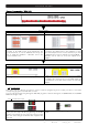
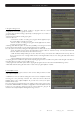
User’s manual · TSF 310 CI ATACHMENT I Depending on the configured parameters we are going to obtain one particular channel capacity (output useful bit rate).
User’s manual · TSF 310 CI Useful channel capacity (8 MHz) Modulation QPSK 16-QAM 64-QAM FEC codification 1/2 2/3 3/4 5/6 7/8 1/2 2/3 3/4 5/6 7/8 1/2 2/3 3/4 5/6 7/8 Guad Interval 1/4 4.976 6.635 7.465 8.294 8.709 9.953 13.271 14.929 16.588 17.418 14.929 19.906 22.394 24.882 26.126 1/8 5.529 7.373 8.294 9.216 9.676 11.059 14.745 16.588 18.431 19.353 16.588 22.118 24.882 27.647 29.029 1/4 4.354 5.806 6.532 7.257 7.62 8.709 11.612 13.063 14.515 15.24 13.063 17.418 19.595 21.772 22.861 1/8 4.838 6.
ESPAÑA Mogoda, 110 Pol. Industrial Can Salvatella 08210 Barberà del Vallès (Barcelona) España Tel. 00 34 93 729 27 00 Fax. 00 34 93 729 30 73 ftemaximal@ftemaximal.com www.ftemaximal.com FRANCE 16 ZAE Les Mouilles 74570 Groisy Tel. 00 33 450 68 80 17 Fax. 00 33 450 68 84 68 sav@ftemaximal.fr www.ftemaximal.com ITALIA Via Edison, 29 42040 Calerno di Sant’Ilario d’Enza (RE) Tel. 00 39 05 22 90 97 01 Fax. 00 39 05 22 90 97 48 fte@fte.it www.ftemaximal.