
User guide
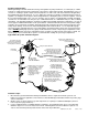
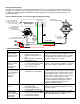

Fuel Filter with 60 Micron or
Lower Particle Rating is Required.
Fuelab Filter with 6, 10 or 40
Micron Rating is Recommended.
Check Valve Required for Reduced
Vehicle Emissions and Improved
Engine Starting. Fuelab 848xx
and 858xx Series Filter has Check
Valve Assembly Built in.
Fuel Straining Filter Required, Typical
Micron Rating: 75-150, Fuelab
75 Micron Filter Recommended.
109020121-1, No Rev Sheet 2 of 6
to Maximum Pump Flow Rate.
Consult Pump Manufacturer's
Specifications and Recommendations.
Vented Fuel Cell or Fuel Tank.
Tank must be Plumbed According
Follow Fuel Cell Manufacturer's
Recommendations for Proper
Cell Vent Plumbing
with Injectors
Fuel Rail
Multiple Rails can be plumbed
using "T" Fitting or "Y" Block.
Dual Inlet Regulator is Not
Required, as Changes in
Flow Rate through
Regulator are Very
Small when Compared
to other Bypass Style
Regulators.
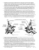
Gauge Port, Liquid Filled
Inlet Fitting
on Left Side
to Temperature Variations.
52901-c Regulator
Gauge may have Error Due
To Engine Intake Manifold
Fuel Gauge Shown in
Return Fitting
on Right Side,
DO NOT REMOVE!
Fuelab Prodigy Series
Fuel Pump REQUIRED!
(Regulator Accepts Up
to Two Prodigy Pumps)
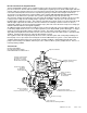
Plumbing Planning Notes:
Minimize plumbing restrictions between fuel rail(s) and regulator for peak performance, use –6AN (3/8”) to –10AN
(5/8”) line as required per flow rate requirements of the vehicle’s engine and fuel pump. EFI applications can use a
“Y” block or “T” fitting to split the output of the fuel pump into one end of each fuel rail (for dual fuel rail application)
then plumbed into the single inlet port. Use of a –6AN (3/8”) return line is typically recommended for this model of
regulator. See diagram on next page as well as diagram below, to identify the ports used on the regulator. The fuel
line used must handle high pressure. The use of fuel line such as stainless steel braided line and “AN” style fitting
connections is recommended. The fuel ports (one –6AN Inlet Port and one –6AN Return Port) use “AN” or “military
”
style fittings. This plumbing standard is commonly used with racing and high performance applications. See step 6
on next page for additional information on this port standard. A fuel filter with a 60 micron or lower particle rating is
required to be used upstream of regulator and downstream from fuel pump to protect it and the fuel injectors from
foreign object damage. Reference the Schematic Diagram below for filter locations. Use of a liquid filled gauge
exposed to engine compartment heat is not recommended as the liquid inside the gauge may exert measurement
errors. DO NOT
plumb gauge port to any gauge mounted inside the vehicle or in passenger compartment. A line
burst can spill fuel inside passenger compartment and on occupants, possibly causing serious injury or death. An
electric gauge or pressure transducer system is recommended for readings in a passenger compartment.
Typical EFI Fuel System Schematic Diagram:
Installation Steps:
1. Disconnect the ground terminal from battery and allow the vehicle’s engine and exhaust system to cool.
Relieve fuel system per applicable service manual. Follow all Warnings and Cautions written on previous page
of these instructions.
2. Modify, remove or replace other fuel system components as required per established build plan (reference
notes on previous page and above).
3. Use the supplied bracket as a drilling template to mark holes for mounting bracket. Choose a location that
minimizes exposure to excessive heat, near fuel rails. Mounting bracket can be modified as required. Use
clear or colored enamel
p
aint to
p
rotect bracket surface after an
y
modification.