
User guide

109020121-1, No Rev Sheet 4 of 6
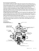
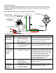
Mates with Included Plug and Wire
4-Pin Connector
(installed)
Adjustment Hardware
Assembly (This Section
Operates as a standard
(installed)
This Fitting can
be Substituted
Standard Inlet Fitting
Pressure Transducer
This Fitting CANNOT
to Build Return Line Back-Pressure
be Substituted!
Relief Valving, Required
Electronics Package
(Used to Monitor
Return Line Back-Pressure)
Return Line Fitting
EFI Mechanical Regulator)
Regulator and Diaphragm
Hardware Shown Installed
(Bagged Separately)
DO NOT DISASSEMBLE!
NO USER SERVICABLE INSIDE!
FOR INFORMATIONAL PUPOSES ONLY!
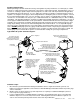
How does the Electronic Re
g
ulator Work?
Just like standard EFI regulators, these regulators begin to relieve pressure (back to the fuel tank) once the set
pressure is achieved. As more and more flow is sent through the regulator (pressure climbs a little higher with extra
amount of flow), the regulator relieves the excess flow back to the fuel tank. Our Patented Electronic Regulator (pe
r
U.S. Patent 7,810,470) takes this action one step further by placing a restriction valve along the return line (a
special valve is incorporated into the return line fitting of the regulator, DO NOT REPLACE this fitting with another
component, as this will force the operation of the system to go into high speed pump operation only).
The electronics monitors the built-up pressure and controls the Prodigy Fuel Pump accordingly. If the pressure that
is being read is too high, then the Prodigy Pump is signaled to slow down. If the pressure is too low, then the
Prodigy Pump is signaled to speed up. This action not only allows the pump to operate at a reduced amount speed
with low engine output, but also allows the return line flow rate to be relatively constant. This has an effect of
negating the regulator’s inherent mechanical regulation slope (This value is the amount of fuel pressure change per
amount of flow rate difference through the regulator).
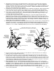
An additional output from the Electronic Regulator can be used to track the fuel system operating condition. This 0-
5 Volt analog output allows the user to use a data acquisition system, Engine ECM, general data logger, or simply a
volt meter, to track how hard the pump is signaled to operate. The voltage is typically at about 1.5 to 2.0 Volts
(depending on Pump Model used and other factors such as baseline fuel pressure) while engine is operating at idle
condition. Typical full capacity has an output of approximately 4.5 Volts.
This regulator controls the fuel pump directly. Because of this, variation of pitch and sound quality radiating from
the fuel pump is to be expected, that is normally absent from traditional EFI fuel systems. Some small amounts of
oscillation during operation may be present at various operating conditions. Initial starting typically calls to the
pump to start in a full speed condition, until fuel pressure is achieved, when speed is greatly reduced. This too is a
normal operating condition.
A Look Inside: