Version: 020341-00-24A-XD
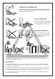
IMPORTANT INFORMATION! please read the entire manual before starting to assemble and/or using this product.follow the manual thoroughly and keep it for further reference. AVOID SCRATCHES! In order to avoid scratching this furnuture should be assembled on a soft layer-could be a rug. IMPROVE EFFICIENCY ! Try to find a partner to install with you, which can speed up the installation efficiency and shorten the time. ANTI-TOPPLE WARNING ! Overturned furniture can cause serious or fatal crush injuries.
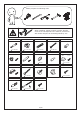
Please prepare the following tools When installing, please carefully confirm whether each screw corresponds to the manual, accessories with similar shapes can be distinguished by size A x 36 +4 C x 57 +4 B x 36 +4 6 x 35 mm Fx2 15 x 10 mm 6 x 30 mm H x 40 +4 Gx2 Ex4 D x 24 +2 4 x 35 mm J x 12 +1 K x 18 +2 K-1 K-2 x2 3 x 14 mm 20 mm Lx2 Mx6 Nx2 Px8 Q x 32 +3 x2 3.
1 2 5 4 7 8 6 9 3 4 ALWAYS install Anti-tip device provided. NEVER put a TV on this product. NEVER allow children to stand,climb or hang on drawers,doors,or shelves. NEVER open more than one drawer at a time. Place heaviest items in the lowest drawers. This is a permanent label.
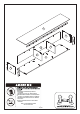
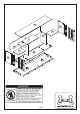
10 13 16 12 15 25 17 14 23 16 18 22 11 19 20 12 26 19 21 22 5/42
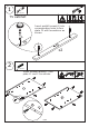
Ax4 1 6 x 35 mm TV cabinet Insert quickfit screw(A) into corresponding holes in two plate 12 with screwdriver as shown. A A 12 12 A x2 C x 10 2 6 x 30 mm Insert wooden dowel(C) into plate 11 and 13 as shown.
Bx2 3 15 x 10 mm Hx2 20 mm Attach plate 12 to plate 13, put cam lock(B) into holes in plate 13 and turn clockwise to tighten as shown. B 13 B 12 H 13 13 180° B Use part(H) to cover cam lock holes as shown. 12 Bx2 4 15 x 10 mm 12 H Hx2 H 13 12 ! 20 mm Attach another plate 12 to plate 11, put cam lock(B) into holes in plate 11 and turn clockwise to tighten as shown. B 11 B 12 H 11 11 180° B 12 H Use part(H) to cover cam lock holes as shown.
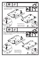
5 Ax8 6 x 35 mm Insert quickfit screw(A) into corresponding holes in plate 10 as shown. A A A A A 10 A 10 A A A 6 Lx2 x2 Fix part(L) to plate 10 as shown.
Bx4 7 15 x 10 mm Cx8 6 x 30 mm Attach the two components to plate 10 with wooden dowel(C),put cam lock(B) into holes in plate 11,13 and turn clockwise to tighten as shown. Insert wooden dowel(C) into plate 14 and 15 as shown.
Bx4 8 Hx4 15 x 10 mm 20 mm Attach plate 14 and 15 to plate 10 with wooden dowel(C),put cam lock(B) into holes in plate 14,15 and turn clockwise to tighten as shown. Stick part(H) to plate 11 and 13 as shown.
Hx4 9 20 mm Connect plate 23 with plastic bar 24 at first. Slide back plate along grooves as shown. Stick part(H) to plate 14 and 15 as shown.
Dx8 10 4 x 35 mm Cover plate 18 to the top and fix using screw(D) as shown.
Ax4 11 K-1 6 x 35 mm K x 18 Tx8 K-2 3 x 14 mm 3 x 12 mm Fix back plate 23 using screw(T) as shown. Reinforce back plate using part(K) as shown. Insert quickfit screw(A) into corresponding holes in plate 18 as shown.
Ax4 12 Cx4 6 x 35 mm 6 x 30 mm Insert quickfit screw(A) into corresponding holes in plate 20 and 21 as shown. Insert wooden dowel(C) into two plate 22 as shown. A A A C 20 20 22 x2 21 C 22 A A C Bx4 13 15 x 10 mm Connect plate 20 and 21 with plate 22, put cam lock(B) into holes in plate 22 and turn clockwise to tighten as shown.
Bx4 14 Cx8 15 x 10 mm 6 x 30 mm Attach the component to plate 18 with wooden dowel(C),put cam lock(B) into holes in plate 22 and turn clockwise to tighten as shown.
15 Nx2 Rotate leg support 19 into plate 18 as shown. Rotate part(N) into leg support 19 as shown.
Q x 32 Px8 16 3.5 x 12 mm Fix part(P) to plate 18, 20 and 21 using screw(Q) as shown.
Jx8 17 Insert part(J) into corresponding holes in plate 11,14,15 and 13, place shelf 16 in as shown.
Jx4 18 Insert part(J) into corresponding holes in plate 14 and 15, place shelf 17 in as shown.
Ex4 19 Fx2 Gx2 x2 Insert part(E) into plate 25 and 26 as shown. Fix part(G) and knob(F) to plate 25 and 26 respectively as shown.
20 10 25 Assembled the two door plate as shown.
21 Adjust leg support as shown.
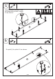
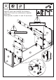
Ax4 22 C x 10 6 x 35 mm 6 x 30 mm Hanging cabinet Insert quickfit screw(A) into corresponding holes in two plate 4 as shown. C Insert wooden dowel(C) into plate 3 and 5 as shown. C 5 C A C C 3 A C C 4 x2 C C C 3 A C 23 Bx2 4 Hx2 15 x 10 mm 20 mm Attach plate 4 to plate 3, put cam lock(B) into holes in plate 3 and turn clockwise to tighten as shown. 3 B 3 B H H 4 4 3 B 4 180° Use part(H) to cover cam lock holes as shown.
Bx2 24 Hx2 15 x 10 mm 20 mm A holes in plate 5 and turn clockwise to tighten as shown. 5 5 B H B 5 H 4 4 180° B Use part(H) to cover cam lock holes as shown. 4 5 H 4 Cx6 25 6 x 30 mm C C C 8 C 8 C C Insert wooden dowel(C) into plate 8 as shown.
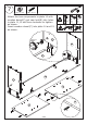
26 A x 12 6 x 35 mm Dx4 4 x 35 mm 4 Attach the two components to plate 8, then fix using screw(D) as shown. Insert quickfit screw(A) into corresponding holes in plate 1 as shown.
Bx4 27 15 x 10 mm Cx3 Mx6 6 x 30 mm 4 x 35 mm Attach plate 2 to plate 1 using wooden dowel(C) and fix with screw(M) as shown. Cover plate 1 to plate 3,5 and 8, put cam lock(B) into holes in plate 3,5 and turn clockwise to tighten as shown.
Bx4 28 Hx8 15 x 10 mm 20 mm Stick part(H) to plate 3,8 and 5 as shown. Put cam lock(B) into holes in plate 8 and turn clockwise to tighten as shown.
29 Bx4 Cx8 15 x 10 mm 6 x 30 mm Attach plate 6 and 7 to plate 1 with wooden dowel(C),put cam lock(B) into holes in plate 6,7 and turn clockwise to tighten as shown. Insert wooden dowel(C) into plate 6 and 7 as shown.
D x 12 30 Hx4 4 x 35 mm 20 mm Cover plate 9 to the unit, then fix using screw(D) as shown. Stick part(H) to plate 6 and 7 as shown.
31 Please use a tape measure to measure the distance between the three wall hanging holes on plate 8 and the distance from the hole center to the bottom of plate 9.
32 Rx3 8 x 40 mm 8 9 Please use the electric drill to lead three holes in the wall according to the value measured in the previous step and the relevant data in this 1100mm step.
33 Sx3 5 x 60 mm Fix the upper cabinet to part(R) on wall through hardware pack(S) as shown.
34 H x 12 20 mm If there is no high cabinet, please use hole sticker (H) to cover the holes on the appearance of the hanging cabinet and TV cabinet respectively. If there is a high cabinet, please skip step 34 and directly install step 35.
35 If there are left and right high cabinets, hanging cabinets and TV cabinets, please install them as shown in the figure below.
36 Left high cabinet Right high cabinet 42 27 Take out shelf 16 and 17,48 from cabinets.
37 Assemble four units together as shown.
38 W x 12 X x 12 6 x 18 mm 6 x 18 mm W Fix them together using hardware pack(W,X) as shown.
39 Place shelf 16 17 and 48 in.
40 Please measure the distance between these holes and the distance from the hole center to the bottom.
41 Drill holes on wall.
42 Rx3 Vx2 8 x 40 mm 6 x 30 mm Knock part(R) and (V) into holes.
Dx2 43 Sx3 4 x 35 mm 5 x 60 mm V D Fix the cabinet to part(R,V) on wall through hardware pack(S,D) as shown.
WARRANTY WARRANTY CLAIMS •There is a 30-day warranty for broken furniture or any other problems that do not work properly. The warranty will start from the date of purchase which must be verified by proof of purchase. •Before making a claim, we may be able to answer your query, simply call us. Please leave your purchase order number, along with some details of the problem, if you want a replacement part. We will arrange within 48 hours. If there is out of stock, we will reply with a shipping date.
RETURNS CHANGED YOUR MIND AND NEED TO RETURN YOU ITEM? PLEASE FOLLOW THE BELOW INSTRUCTIONS: •If you have purchased and have simply changed your mind, follow the retailer’s instructions for returns. DEFECTIVE ITEMS •If your item is defective in any way, i.e. it doesn’t work but you can’t identify why, in the first instance, please call us. DAMAGED ITEMS •If you receive an order with obvious shipping damage from the retailer, then we suggest the delivery is refused.