
Installation Guide

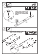

3
4
7/42
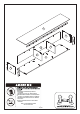
11
11
11
11
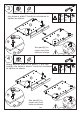
13
13
13
13
12
12
12
12
12
12
B
B
B
B
180°
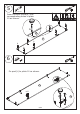
H
H
H
H
H
H
B
!
!
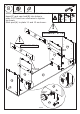
Attach plate 12 to plate 13, put cam lock(B)
Use part(H) to
cover cam lock
holes as shown.
into holes in plate 13 and turn clockwise to
tighten as shown.
15 x 10 mm
B x 2
20 mm
H x 2
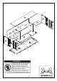
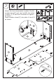
12
B
180°
12
Attach another plate 12 to plate 11, put cam
lock(B) into holes in plate 11 and turn clockwise
to tighten as shown.
Use part(H) to
cover cam lock
holes as shown.
15 x 10 mm
B x 2
20 mm
H x 2