FUJI Digital Quatro Correlator Quattro Core LC-5000 Instruction Manual
Preface This is the instruction manual for the FUJI Digital Quatro Correlator, Quatro Core LC-5000. Be sure to read these instructions before using the equipment to ensure that you understand how to use it correctly. Application The LC-5000 correlation-type leakage detector is used by mounting preamplifier-integrated sensors to fittings such as fire hydrants, valves, or meters on the underground pipe to capture the sound of water leakage and detect the locations of leaks.
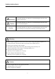
Safety Instructions This symbol indicates the existence of a potential danger that could cause Warning death or serious injury. This symbol indicates the existence of a potential danger that could cause Caution Caution minor or moderate injuries. This symbol indicates the existence of a potential danger that could cause serious damage to the equipment or damage to surrounding property.
Safety Instructions Caution ● Do not leave or install the equipment in a hot place. (This may cause a malfunction.) ● Do not use this equipment for any purpose other than leak detection. ● The main unit is dust-proof and drip-proof, but not completely waterproof. Do not submerge it water or use it in bad weather. ● Do not drop the equipment or subject it to strong impact. ● Do not attempt to disassemble the equipment. ● Remove the battery if the device will not be used for an extended period of time.
Safety Instructions Compliance statement to FCC/IC This module complies with part 15 of the FCC rules and IC RSS-210. Operation is subject to the following conditions: (1) This device may not cause harmful interference, and (2) this device must accept any interference received, including interference that may cause undesired operation. Warning Changes or modifications not expressly approved by the party responsible for compliance could void the user’s authority to operate the equipment.
Safety Instructions (4) Markings To satisfy FCC/IC exterior labeling requirements, the following text must be placed on the exterior of the end product. Contains Module FCC ID: 2AARD-LC50, IC: 11320A-LC50 Any similar wording that expresses the same meaning may be used. (5) Caution to user for modification The following caution is expressed on the user’s instruction manual.
Warranty Period The warranty period is one year from the date of purchase. The warranty card is intended to ensure we can provide you with the highest level of service. Please enter your name and address on the warranty card. If a defect occurs in the functioning of the device during the warranty period, it will be repaired free of charge. You will be required to present the warranty card for repairs during the warranty period, so please keep it in a safe place.
Table of Contents 1. Components..................................................................................................................... 9 1−1 List of Components .......................................................................................... 10 1−2 Optional Accessories ........................................................................................ 12 2. Description of Equipment .............................................................................................
Table of Contents 6. Techniques for Using the Equipment ............................................................................ 74 6−1 Pipe Data Handling (Main Unit) ...................................................................... 75 6−2 FFT Screen Function (Main Unit) .................................................................... 77 6−3 White Noise Method ........................................................................................ 78 6−4 Leak Noise Record Function ...........
1.
1−1 List of Components The equipment consists of the components indicated below. After purchase, check to make sure you have each component. If any of the components are missing, please contact FUJI TECOM immediately.
1−1 List of Components ● Charger for rechargeable battery in main unit × 1 ● AC adapter for preamplifier-integrated sensor × 4 ●● ● SDHC card (class 10) × 1 ● Instruction manual (CD) × 1 ● Post process software × 1 Storage case × 1 11
1−2 Optional Accessories The following optional items are available for this equipment and may be purchased if needed. Please contact our sales representative to make your purchase. ● External sensor (pipe wall) ● Coupling-type hydrophone sensor ● Wired cable (10 m reel) ● Spare rechargeable battery for main unit * All the optional accessories are available on a made-to-order basis.
2.
Panel and Switches (Main Unit) (1) Main unit (front panel) (1) Main unit (front panel) ① Menu switch ⑤ Correlation switch Display the menu. Perform correlation processing. ② Help switch ⑥ Filter switch Display the help screen. Display the main unit filter setting screen. ③ Pre-amplifier switch ⑦ Setting pipe conditions switch Display the pre-amplifier setting screen. Display the pipe condition setting screen. ④ SDHC card slot ⑧ Return switch Insert the SDHC card.
2−1 Panel and Switches (Main Unit) (2) Main unit (top panel) (2) Main unit (top panel) ① ② ① Cable 1 connector ③ ④ ③ Power switch To use the pre-amplifier in cable mode, plug in the cable here. Turn on the unit. ④ Headphone jack ② Cable 2 connector Plug in the headphones to listen for the sound of water leakage through the headphones. To use the pre-amplifier in cable mode, plug in the cable here.
Panel and Switches (Pre-Amplifier) (1) Pre-amplifier (top panel) (1) Pre-amplifier (top panel) ③ ① ② ④ ⑤ ⑥ ⑦ ⑨ ⑧ ① Power LED ⑥ Sensitivity up switch Lights up when the power is turned on. Increases sensitivity. ② Mode LED ⑦ Sensitivity down switch Indicates the mode of operation. Decreases sensitivity. * If you press and hold one of the sensitivity switches, the LED will fully illuminate and auto-adjust will execute. ③ GPS LED Indicates the GPS status.
2−2 Panel and Switches (Pre-Amplifier) (2) Pre-amplifier (side panel) (2) Pre-amplifier (side panel) ① ② ③ ① AC adapter jack for charging ③ External sensor connector Insert the AC adapter for charging. Insert the external sensor. ② Cable connector Connect to the main unit for wired use.
Explanation of Pre-Amplifier LEDs (1) Display of LEDs during operation (1) Display of LEDs during operation Function*1 Power LED color Red/yellow Mode GPS Green Power OFF Battery replacement warning*2 Charging*3 Unlit Flashing N/A (henceforth, —) Lit — Radio channel display — — See P.
(2) Radio channel (3) Display of power LED during charging 2−3 Explanation of Pre-Amplifier LEDs (2) Radio channel Function Power Mode LED color Red/yellow GPS Sensor Green N/A (henceforth, —) ○ ○ ● Radio channel 2 ○ ● ○ Radio channel 3 ○ ● ● ● ○ ○ Radio channel 5 ● ○ ● Radio channel 6 ● ● ○ Radio channel 7 ● ● ● Radio channel 1 Radio channel 4 — ● Lit ○ Unlit (3) Display of power LED during charging When power is on When power is off Not charging Charging Battery re
3.
Checking and Replacing the Battery (Main Unit) (1) Checking the battery power (2) Opening and closing the battery cover and replacing the battery (1) Checking the battery power ● Make sure that the battery level is high enough before use. When checking the battery level, turn on the main unit. When the battery is not fully charged, you will see empty space inside the battery power indicator as shown on the left.
Backup Battery Since the data is stored on the SDHC card (Class 10), there is no need a backup power source for data retention. The main unit has a built-in rechargeable battery for clock operation. This battery is automatically charged when the rechargeable battery (RRC2020) is inserted. Please note that the date and time will not show correct values if the clock battery runs out. After the main unit has been turned off for a long period, check the date and time for correctness after power-on.
Pre-Amplifier Battery Check (1) Checking the battery power (1) Checking the battery power ● Be sure to check all four pre-amplifiers: blue, red, yellow, and green. ● Make sure that the battery level is high enough before use. When checking the battery level, turn on the pre-amplifier and the main unit. Check the remaining battery levels of the blue, red, yellow, and green units on the main unit screen. If the battery level is low, insert the charging AC adapter to charge the battery.
Pre-Amplifier Check There are four pre-amplifiers (blue, red, yellow, and green). Check each pre-amplifier in the same way. ① Press the power switch. ② Connect the headphones to the pre-amplifier. ③ Lightly rub the magnet at the bottom of the pre-amplifier and verify that sound can be heard from the headphones. If the sound is not audible, there may be a problem with the sensitivity of the sensor. Compare it with the other pre-amplifiers.
General Check (1) Main unit and pre-amplifier radio check ⑥ Verify that the console shows an icon of the same color as the pre-amplifier. If the icon is not displayed, the main unit is not receiving the radio signal. Check the following: (1) Main unit and pre-amplifier ① Turn on the main unit. ② Press the menu switch . ● If the radio signal is not being received due to the surrounding environment, tap the radio channel under Common setting to change it as described earlier.
3−5 General Check (2) Correlation calculation check (2) Correlation calculation check Note ① Turn on the main unit. ● Do not rub the pre-amplifier too strongly. Otherwise, the delay time may not be 0.00 ms. ② Turn on two pre-amplifiers. ● If the unit is on its pedestal, or the magnet is dirty, the delay time may not be 0.00 ms. ③ Make sure the data arrival rate is not 0 and then press the correlation switch . ④ Lightly rub the magnet at the bottom of each pre-amplifier.
Date and Time Adjustment The year, month, day, hour and minute are displayed in the upper right corner of the screen. Check whether the date and time are correct. If the date and time are incorrect, adjust them using the following procedure. The date and time are saved together with the measurement data, so make sure they are set correctly. Press the main unit menu switch . Tap "Equipment setting" under Menu. Tap “Date & time” under Equipment setting.
4.
(1) Radio mode (2) Cable mode Radio and Cable Modes (1) Radio mode Leak location (2) Cable mode Cable mode is used when radio communication cannot be established between the leak detector and the pre-amplifiers due to interference from buildings or other radio stations etc. Normally, leak detection is done in radio mode as shown in (1) above.
Example of Detecting a Leak in a Pipe This section explains how to perform leak detection for the pipe shown below. In this example, it is assumed that the water leaks from a certain location in the pipe. The pre-amplifiers detect the leak noise and send the signals to the main unit.
False Leak Noise When the pre-amplifiers detect sound other than the sound of water leakage, the correlator will sometimes misinterpret the sound and display it as the leak location. When the correlator reports a leak, you should confirm the leak with other leak detection equipment, confirm by boring and investigate how the pipe is buried.
(1) Radio mode preparations (2) Cable mode preparations Preparations (1) Radio mode preparations Pipe length (2) Cable mode preparations (cable reel and connecting cable are sold separately) Leak location Leak location ● Insert the rechargeable battery into the main unit. ● Insert the rechargeable battery into the main unit. ● Attach the antenna to the main unit and pre-amplifier. ● Attach the antenna to the main unit and pre-amplifier. ● Turn on the main unit and the pre-amplifiers.
(1) Preparation of necessary conditions and data (2) Installation of pre-amplifiers Preparation at Site (1) Preparation of necessary conditions and data (2) Installation of pre-amplifiers ① Candidate installation locations include fire hydrants, gate valves, and meters. Determine the installation locations and install the pre-amplifiers. To find the location of the leak with the correlator as shown in the figure below, the necessary data is required, and the following four conditions must be met.
4−5 Preparation at Site (3) Installation of antennas Caution Connect the antenna and extension cable securely. If water enters the pre-amplifier through the connectors for the antenna and extension cable, it may cause a serious failure. If you do not connect the antenna and extension cable, cover the connectors with the supplied caps to ensure waterproofness. (3) Installation of antennas In general, the higher the antenna is installed, the more vulnerable the signal is to radio interference.
4−5 Preparation at Site (4) Precautions when using the pre-amplifier (4) Precautions when using the pre-amplifier Note ● The pre-amplifier is equipped with a radio.
(1) Switches on the main unit (2) Touch panel operation Main Unit Switches and Operation ● Other screens Displays the multi-correlation stopped screen. (1) Switches on the main unit Menu switch Filter switch Toggle the display of the menu on each display screen. Display the main unit filter setting screen. Help switch Setting pipe conditions switch Display the help screen for the current screen. Display the pipe condition screen.
Explanation of Equipment Settings and Operations Press the pre-amplifier switch . Tap the icon of the pre-amplifier to be configured. Alternatively, tap the "All" tab to simultaneously configure a group of common settings (operation mode, recording start time, filter, sensitivity, GPS). The All tab shows only settings that match all the pre-amplifiers. Changing the Operation Mode The pre-amplifiers function as radio relays.
4−7 Explanation of Equipment Settings and Operations Setting the Recording Start Time This setting configures the recording start time in logger mode. It can be set within a 24-hour range. Tap the value for Start time and then set the value in the 24-hour display. You cannot tap this unless the Logger mode is selected as the Mode. Filter Settings The logger has two filters available: Common and Through. The default setting is Common. Tap Common to change it to Through.
4−7 Explanation of Equipment Settings and Operations GPS Setting You can toggle the GPS setting. The default setting is ON. If you do not want to use GPS, tap ON to switch it OFF. Sending Settings When all the pre-amplifier settings are complete, tap Send settings to send the settings to the pre-amplifier.
4−7 Explanation of Equipment Settings and Operations Press the setting piping conditions switch . Pre-Amplifier Combination Settings Select the combination of pre-amplifiers whose pipe conditions are to be set. Tap the icons of the pre-amplifiers. Select a combination of pre-amplifiers from the Target pre-amplifier set selection screen.
4−7 Explanation of Equipment Settings and Operations Adding or Changing Pipe Conditions To add or change the pipe type (material), diameter, or length, tap the corresponding box and enter the value. Select a material. For the list of materials, see "6-1 Pipe Data Handling (Main Unit)" on p. 74. Tap “Delete” to delete the information. When a row of data is deleted, the rows below it are shifted upwards. Select a diameter.
4−7 Explanation of Equipment Settings and Operations Sound Velocity Registration This function is for manually setting the sound velocity value. Tap Velocity save. From the sound velocity registration settings screen, select Velocity registration or Velocity calculation. When Velocity registration is selected Enter a velocity value and tap Registration. When Velocity calculation is selected Enter the required information and tap Registration.
4−7 Explanation of Equipment Settings and Operations Setting the Detection Accuracy The detection accuracy can be set to Common or High precision. The default setting is Common. Tap Common to change it to High precision. Select detection accuracy. Setting the Td Range This function sets the Td range (delay time). Tap the value for Td range. Select a Td range from the following choices.
4−7 Explanation of Equipment Settings and Operations Press the filter switch . Setting the Td Range Tap the value for Td range. Select a Td range from the following alternatives.
4−7 Explanation of Equipment Settings and Operations Setting the High Pass Filter Tap the value for High-pass filter. Select a high pass filter from the following alternatives. Through, 80 Hz, 180 Hz, 380 Hz, 800Hz, or Large caliber Setting the Low Pass Filter Tap the value for Low-pass filter. Select a low pass filter from the following alternatives.
4−7 Explanation of Equipment Settings and Operations Setting the Notch Filter Tap the value for Notch filter. Select a notch filter from the following choices. OFF, 50 Hz, or 60 Hz Setting the Detection Accuracy The detection accuracy can be set to Common or High precision. The default setting is Common. Tap Common to change it to High precision. Starting Recording Tap Recording to start recording with the filters you set.
4−7 Explanation of Equipment Settings and Operations Press the menu switch . Tap Leak location screen under Menu of FFT screen. Press the correlation switch . Switching between Multiple and Single Correlation When the correlation screen opens, either the multiple correlation screen or the single correlation screen is displayed. Tap the graph area to switch between the single correlation screen and the multiple correlation screen.
4−7 Explanation of Equipment Settings and Operations Zooming and Moving the Cursor on the Single Correlation Screen ① Zoom out along the X axis (horizontal axis) ② Zoom in along the X axis (horizontal axis) ③ Zoom out along the Y axis (vertical axis) ④ Zoom in along the Y axis (vertical axis) ⑤ Move the cursor far to the left ⑥ Move the cursor to the left ⑦ Move the cursor to the right ⑧ Move the cursor far to the right Starting and Stopping Correlation Processing Press the corre
4−7 Explanation of Equipment Settings and Operations Saving Correlation Data Tap the right edge of the correlation screen to display the quick menu. Tap the SD card icon to save the data under the number that is shown. If you want to specify where to save the data, press the menu switch . Tap Save under Menu. A list of file numbers appears. Tap the number you want to save the data under, or enter a number in the Number box, and then tap the Save button.
4−7 Explanation of Equipment Settings and Operations Recording Sound Data You can record sound data during correlation processing. To start recording with the filters you set, tap the right edge of the correlation screen to display the quick menu. Tap the recording icon to start recording from the point you tapped. The data is saved in the next available file number, which is shown on the screen. Recording ends after 300 seconds or when correlation stops.
4−7 Explanation of Equipment Settings and Operations Listening for Leaks To listen to the sound of each pre-amplifier from the headphones connected to the main unit, tap the right edge of the correlation screen to display the quick menu. Tap the icon corresponding to the headphone you want to listen to. You can adjust the volume you hear from the headphones by tapping + or -.
4−7 Explanation of Equipment Settings and Operations This function performs FFT (Fast Fourier Transform) processing. For an explanation of FFT, see “8-1 Definitions” on p. 90. Press the menu switch in the phase correlation processing screen. Tap FFT screen. Switching between Multiple and Single FFT This operation is the same as for correlation processing. See p. 45. Zooming and Moving the Cursor on the Single Correlation Screen See p. 46.
4−7 Explanation of Equipment Settings and Operations Changing the Frequency Range Press the menu switch . Tap Frequency range. Select a frequency. Changing the Graph Display Press the menu switch . Tap X axis scale. Select an X axis scale.
4−7 Explanation of Equipment Settings and Operations These operations are for processing the stored correlation data, recorded data, waveform data, or white noise data, or for initializing the SD card. Attaching Check Marks to Data Press the menu switch . You can attach check marks to saved data files to identify them as important. Tap Data processing. Select the content to be processed.
4−7 Explanation of Equipment Settings and Operations Playback and Correlation of Recorded Data This function lets you can listen to the data recorded on the main unit with headphones. It also enables correlation processing. Press the menu switch . Tap Data processing. Tap Recording data. Tap the file or enter the file number in the Number box and then tap the Playback button or the Correlation button.
4−7 Explanation of Equipment Settings and Operations Graphing the Leakage Location Data Press the menu switch . Tap Data processing. Tap Leakage location data. * The same procedure is used to graph the FFT data and white noise data. Tap the file or enter the file number in the Number box to be graphed and then tap the Display button. A graph is displayed based on the saved data. Zooming and cursor operations can be performed in the same way as common correlation.
4−7 Explanation of Equipment Settings and Operations Recalculating the Leakage Location Data You can change the pipe length in the saved leakage location data and recalculate the distance to the leak location. Press the menu switch . Tap Pipe conditions. Change the length in the displayed pipe conditions. When you are done, click × in the top right to close the Setting piping conditions screen.
4−7 Explanation of Equipment Settings and Operations Formating the SD Card (Class 10) Press the menu switch . Tap Data processing. Tap SD card format. Tap OK on the Confirmation screen.
4−7 Explanation of Equipment Settings and Operations This function collects the recorded data stored on the pre-amplifier and saves it to the main unit. Press the menu switch . Tap Logger-data collection. Tap the file you want to save the data or enter the file number in the Number box and then tap the Start button. The recorded data is collected from the connected pre-amplifier via wireless communication.
4−7 Explanation of Equipment Settings and Operations System information Press the menu switch . Tap Equipment setting. Tap the Display button. Information on the main unit is displayed. RF Unit ID: Number related to the country of use CPU version: Firmware version of the main unit Radio version: Radio firmware version Tap a pre-amplifier icon to display the information for that pre-amplifier.
4−7 Explanation of Equipment Settings and Operations Luminance Setting Press the menu switch . Tap Equipment setting. Tap the Luminance up/down buttons. Up: brighter. Down: darker.
4−7 Explanation of Equipment Settings and Operations Power Saving Setting This function reduces the screen brightness after the specified time has elapsed to reduce battery consumption. Tap the screen or press an external switch to return to normal brightness. Set the length of time before power saving mode takes effect. Press the menu switch . Tap Equipment setting. Tap the Power saving box.
4−7 Explanation of Equipment Settings and Operations Language Setting Press the menu switch . Tap Equipment setting. Tap the Language box. Configure the setting on the make changes screen, and then tap the × in the upper right corner.
4−7 Explanation of Equipment Settings and Operations Changing Radio Channel This function lets you use a different radio channel. The wireless connection is temporarily interrupted while changing the radio channel connecting the pre-amplifier to the main unit. Press the menu switch . Tap Equipment setting. Tap the Radio channel box. Configure the setting on the make changes screen, and then tap the × in the upper right corner.
4−7 Explanation of Equipment Settings and Operations Change Time Zone The date and time obtained from GPS is based on UTC (Coordinated Universal Time). When using the logger mode of the pre-amplifier, you need to set the time zone. If the time zone is set incorrectly, recording will not start at the desired time. Use the instruction manual or the Internet to set the appropriate time zone. Press the menu switch . Tap Equipment setting. Tap the Time zone box.
5.
Common Correlation Detection Method ① Turn on the pre-amplifiers. ⑦ Install the pre-amplifier on the valve etc. at the installation location. ② Turn on the main unit. ⑧ Press and hold the sensitivity up or down ③ Verify that the pre-amplifier icons are lit. switch on the pre-amplifier to perform automatic adjustment. If you are unable to press the sensitivity switch on the pre-amplifier, turn on "Auto-sens." in the pre-amplifier settings on the main unit and then tap Send settings.
5−1 Common Correlation Detection Method ⑪ Press the menu switch ⑮ Verify that the pre-amplifier icon on the main unit is lit, and then press the correlation . switch ⑫ Tap “Leak location screen” to switch from the FFT display to the leak location screen. . ⑯ Correlation processing starts and the screen is updated. The number next to the SD card icon is the number of additions. ⑬ Verify that the pre-amplifier icon is lit, and then press the Setting piping conditions switch .
(1) Using the pre-amplifiers to listen for leaks (2) Listening on the main unit Listening for Leaks (1) Using the pre-amplifiers to listen for leaks (2) Listening on the main unit ① Connect the headphones to the main unit and verify that the headphone icon is displayed on the screen. To avoid damage to your ears, do not wear the headphones when connecting them to the headphone jack. Connect the headphones to the headphone jack to listen for leakage sound.
From Configuration of Logger Mode to Completion of Measurement Work outdoors to get the signal directly from the GPS and adjust the time. A location that is away from roofs or buildings and open to the south is recommended to reduce the time it takes to complete the sync (at which point the GPS LED illuminates). Also, because the GPS is located directly under the switch, if it is covered or if you check it continuously, the sync may take longer to complete. ⑤ Press the menu switch .
5−3 From Configuration of Logger Mode to Completion of Measurement ⑪ Set the filter and the recording start time. ⑭ Verify that all the LEDs on the pre-amplifier are lit. If all the LEDs are lit, the transition to logger mode was successful. If there is a pre-amplifier that is not lit, try setting the pre-amplifier again. ⑮ Turn off the main unit. When the main unit is turned on, the main unit and the pre-amplifiers communicate wirelessly.
Collection of Recorded Data Transfer the data recorded in the pre-amplifier to the main unit. Correlation of the transferred data can be done using the Correlation function (correlation from recorded data). For details on the correlation function, see "Playback and Correlation of Recorded Data" under "4-7 Explanation of Equipment Settings and Operations" on p. 53. ⑥ Tap Logger-data collection. ① Turn on the pre-amplifiers. ⑦ The list of recorded data is displayed.
5−4 Collection of Recorded Data ⑨ After the logger data is collected, the list of recorded data is updated. When you are done collecting the logger data, press the menu switch to move on to other tasks.
6.
Pipe Data Handling (Main Unit) Using four pre-amplifiers, correlation processing for up to six routes can be performed. Leak location Leak location Leak location Pre-amplifier Red (2) Pre-amplifier Blue (1) PE1 20 PE1 20 3.5m In this example, there are three types of pipes as shown in the figure at left. The same applies when using four pre-amplifiers. 4.9m DIP75 41m You can enter six types of pipe data into the fields A through F.
6−1 Pipe Data Handling (Main Unit) For details on entering the pipe conditions, see "Setting piping conditions" under "4-7 Explanation of Equipment Settings and Operations" on p. 38. The types of pipe and their diameters are listed below.
FFT Screen Function (Main Unit) This function uses the DSP (Digital Signal Processor) on the main unit to perform FFT (Fast Fourier Transform) frequency analysis on the leak noise data obtained by the pre-amplifier. This function can be used to analyze the frequency components of the leak sound obtained by the pre-amplifiers, which can be useful when configuring the filter settings (manually).
White Noise Method - Principle of the white noise method - To detect the location of a leak with the correlator, it is necessary to know the following data about the pipes: the pipe material, the pipe diameter (sound velocity), and the distance between the pre-amplifiers. Measurement is not possible if any of the above three items are missing.
6−3 White Noise Method - Case ① Press the menu switch . Tap “White noise” to display the screen on the left. Since the length of the pipe is known but the sound velocity is unknown, tap Find the sound velocity. The screen on the left is displayed. Tap the pre-amplifier to be used and enter the pipe length. Tap "Run". The correlation screen appears and the sound velocity is calculated. Pause at an appropriate time and save the sound velocity value.
6−3 White Noise Method - Case ② Press the menu switch . Tap “White noise” to display the screen on the left. Since the pipe material and pipe diameter are known but the pipe length is unknown, tap Find the pipe length from the pipe information. The screen on the left is displayed. Tap the pre-amplifier to be used and enter the pipe material and diameter. Tap "Run". The correlation screen appears. The calculated distance is displayed next to the pre-amplifier icon.
6−3 White Noise Method - Case ③ In this case, since both the pipe diameter (sound velocity) and pipe length are unknown, the sound velocity value obtained from the pipe material type is input as an estimated value to temporarily detect the leak location. Refer to the table below for a list of sound velocities. ● In general, the speed at which the leaked sound propagates in the pipe varies depending on the material and diameter.
6−3 White Noise Method The correlation screen appears. The calculated distance is displayed next to the pre-amplifier icon. Enter this value as the pipe length in the pipe data. Note The distance L obtained in this way is calculated from the estimated sound velocity and therefore should be treated as an approximate value.
Leak Noise Record Function This function lets you record and replay the leak noise data collected with the pre-amplifiers. The frequency analysis can also be executed at the same time using the FFT screen function. During recording and playback, you can see the frequency analysis results on the FFT screen while listening to the leak noise.
Evaluation of Detected Position The evaluation is displayed at the lower left of the waveform graph on the leak location screen. This is an evaluation of the degree of correlation based on the results obtained from leak detection. The evaluation is divided into the three grades A, B, and C as follows: A: High confidence B: Medium confidence C: Low confidence The evaluation here is based only on the correlation waveform, so it should only be used as a guideline for detecting the leak location.
Automatic Filter Automatic filter is a function that automatically configures the filter settings on the main unit. This function performs an FFT calculation on the leak noise signals sent from each pre-amplifier, processes the frequency components under certain conditions, and sets an appropriate filter value. Basically, the filter value is set so that the main frequency components of the leak noise data acquired by each pre-amplifier are included.
Notch Filter The notch filter can be set to OFF, 50 Hz, or 60 Hz. OFF is the normal setting. Use the notch filter when you hear a buzzing sound from your headphones or speakers, such as the sound of a power pole transformer or a compressor in a vending machine. For details on configuring the notch filter, see "Filter setting" under "4-7 Explanation of Equipment Settings and Operations" on p. 42. Below is a brief description of the different types of filters.
Manual Calculation of Sound Velocity The main unit stores the sound velocity values of various pipes in its internal memory. The built-in values cover the basic pipe materials and diameters that are used, but might not cover all the applications that can be encountered.
Data Transfer to PC Using SD Card Data (leakage location data, FFT data, and leakage noise data) is stored on the SD card. Be sure to insert the SD card when using the correlator. The data stored on the SD card can be processed on a PC using the dedicated software LC-50W for Windows. Follow the instructions in the LC-50W for Windows instruction manual.
7.
7−1 Storage Method When this correlator will not be used for an extended period of time, store it according to the following procedures. ① Make sure that you have all the components including the operating instructions. ② Remove the battery. ③ Do not store the equipment in a damp place. Storage after use Please observe the following precautions for storage after use. ① Clean the mud and dirt from each pre-amplifier and put it in the storage case.
8.
Definitions ● FFT (Fast Fourier Transform) In technical terms, the FFT operation calculates the Fourier coefficients of the Fourier series. The leak detector digitally samples the input signal waveform, stores it as data, performs the FFT operation, and displays the result. The data acquired by the pre-amplifier is time-dependent, and it is difficult to analyze the frequencies in this kind of raw data.
Principle of Leak Noise Correlator — Calculation of leak location — Below is a brief description of the principle of the leak noise correlator. Pre-amplifier (blue) Assume that the leak location is near the red pre-amplifier. The sound of water leakage from the leak location is first obtained by the red pre-amplifier. The sound propagates in both the red and blue directions from the leak point. The propagation speeds are identical.
Specifications of Main Unit ● Applicable standards: ● Storage temperature range: ● Storage humidity range: ● Operating temperature range: ● Operating humidity range: ● External dimensions: ● Weight: ● Battery: ● Continuous operation time: ● Display: ● Controls: ● Interface and terminals: ● Input: ● Functions Correlation function Calculation method: Delay time range: Delay time range: Time resolution: Time resolution: Protection grade IP52 (LCD surface at top) Radio Act (Japan) Vibration/Shock JIS C
8−3 Specifications of Main Unit Average processing iterations: 999 High-pass filter: Through, 80 Hz, 180 Hz, 380 Hz, 800 Hz, Large caliber Low-pass filter: 630 Hz, 1250 Hz, 2500 Hz, 5000 Hz, Large caliber Notch Filter: OFF, 50 Hz, 60 Hz Automatic filter Save calculation results Search function Zoom function Pipe conditions: Pipe type, pipe diameter (XXXX mm), sound velocity (XXXX m/s), Pipe length (XXXX.
Specifications of Pre-Amplifier ● Applicable standards: ● Storage temperature range: IP68 equivalent Radio Act (Japan) Vibration/Shock RoHS -25 to 60°C JIS C 60068-2-6/-2-27 ● Operating temperature range: -20 to 50°C ● External dimensions: 73 mm diameter (80 mm maximum protrusion) x 183 mm (H) * Excluding antenna and handle ● Weight: Approx.
9.
9−1 Troubleshooting Use the procedures described in this chapter when trouble occurs in the operation of the leak detection system. If the appropriate troubleshooting does not restore the equipment or the problem is not covered in this chapter, please contact your agent company. ① If the main unit does not turn on: ● Make sure the battery is inserted. ● Replace the battery with a charged one. ② If the pre-amplifier does not turn on: ● Try charging the battery.