st Instruction manual Fusion Splicer Please read this instruction manual carefully before operating the equipment. Adhere to all safety instructions and warnings contained in this manual. Keep this manual in a safe place. There is a change without a previous notice. We are not responsible for the products which are not purchased from our authorized distributors.
Please consent beforehand. Copying some or all of instruction manual without notice is forbidden. Moreover, without permission from our company, it cannot use on the Copyright Act except that it uses as an individual.
Table of Contents Safety Information ........................................................... 1 General information......................................................... 6 Introduction ...................................................................................................... 6 New function of 12S ......................................................................................... 7 Description of Product ..................................................... 8 Components of Splicer ..
Table of Contents Heater Menu ................................................................. 50 Select Heater Mode ........................................................................................ 50 About heating of a connector splice part......................................................... 53 Setting Menu ................................................................. 54 Splice Settings ...............................................................................................
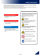
Safety Information The splicer has been designed for splicing Silica-based optical fibers for telecommunications. Do not attempt to use this machine for other applications. Fujikura Ltd. gives much consideration and regard to personal injury. Misuse of the machine may result in electric shock, fire and/or serious personal injury. Follow all safety instructions Read and understand all safety instructions.
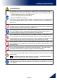
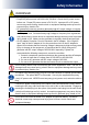
Safety Information WARNINGS! Disconnect the AC power cord from the AC adapter inlet or the wall socket (outlet) immediately if user observes the following or if the splicer receives the following faults: • Fumes, bad smell, noise, or over-heat occurs. • Liquid or foreign matter falls into cabinet. • Splicer is damaged or dropped. If this occurs, ask our service center for repair.
Safety Information WARNINGS! Use only proper power source. • Proper AC power source is AC100-240V, 50-60Hz. Check the AC power source before use. Proper DC power source is DC10-12V. Improper AC or DC power source may cause fuming, electric shock or equipment damage and may result in personal injury, death or fire. • AC generators commonly produce abnormally high AC output voltage or irregular frequencies. Measure the output AC voltage with a circuit tester before connecting the AC power cord.
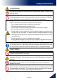
Safety Information WARNINGS! Do not touch the splicer, AC power cord and AC plugs with wet hands. This may result in electric shock. Do not operate splicer near hot objects, in hot temperature environments, in dusty / humid atmospheres or when water-condensation is present on the splicer. This may result in electric shock, splicer malfunction or poor splicing performance. When using optional battery, follow the instructions below. Failure to follow these may result in explosion or personal injury.
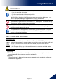
Safety Information CAUTIONS! Follow the below listed instructions for handling electrodes. • Use only specified electrodes. • Set the new electrodes in the correct position. • Replace the electrodes as a pair. Failure to follow the above instructions may cause abnormal arc discharge. It can result in equipment damage or degradation in splicing performance. Do not use any chemical other than pure alcohol (99% or greater) to clean the objective lens, V-groove, mirror, LCD monitor, etc., of the splicer.
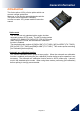
General information Introduction This fusion splicer 12S is a fusion splicer which can connect a single optical fiber. Moreover, a new function was added and made the 12S splicer much improved in versatility. In order to master 12S, please read this instruction manual. Splice mode The 12S has not only standard splice modes, but also automatic modes, AUTO mode. The AUTO mode consists of [SM AUTO], [MM AUTO], [NZ AUTO] , [DS AUTO] mode. When using AUTO mode, the automatic arc calibration function is enabled.
General information New function of 12S Corresponds to connector splice The connection of a field assembly optical connector by heating of a protection sleeve can be performed by a 12S. Moreover, versatility is improved by portability. Corresponds to Short length splice In addition to the standard splice, splice of 5-mm interference also recently became possible. A specialized tool is needed in order to perform 5-mm prepared.
Description of Product Components of Splicer Standard Equipment The standard equipment of the splicer is the following. Check the equipment items mentioned of list. Standard Package List.
Description of Products Other Necessary Items for Splicing Operation Tools Fiber coating diameter UV Coating 0.25mm Standard sleeve 60mm length [FP-03] 40mm length [FP-03 (L = 40)] Ny Coating 0.
Description of Products Description and Function of Splicer structure Tube heater Guide Pin Wind Protector LED Clamp LCD monitor Sheet Key Clamp LED Electrode cover Electrode Objective lens V-groove Holder Base Holder Base V-groove Objective lens Electrode Electrode holder Wind protector Tube heater Protector Protector USB port AC power port 10 12S_Rev1
Description of Products Operation of Sheet Key The outline view of a sheet key ON/OFF key ESC key Key Symbol UP/DOWN key ENT key HEAT key SET key RESET key Key Indicates Key Name Key Function ON/OFF Power key To turn ON/OFF the power. Up/Down Arrow Keys To adjust the brightness of the monitor screen at the ready state. These arrows are used to move the cursor for selecting the items at the menu state, or to change the value or letter of the discharge conditions and comments.
Basic Operation Splicing work preparation The space for working is secured. The work environment according to various uses can be made from using the carrying case of this equipment, and a work tray. Use a work tray Position of belt to attach Where a carrying case lid is opened, work can be started immediately. If a work tray is taken out and a belt was used, it can work as a simple working table. The carrying case itself can be used as a working table.
Basic Operation Power Supply This section describes the procedures for using the power supply with the equipment. Splicer is operated with AC adapter (ADC-19) or the internal battery. Use the only external AC adapter (ADC-19) and AC Coad (ACC-**) with Splicer. AC Coad [ACC-**] AC Adapter [ADC-19] AC Operation Insert AC cord into the AC inlet of the AC adapter. The power ON LED of the AC adapter changes green color when suitable AC voltage is supplied.
Basic Operation Battery Operation Check the remaining battery capacity. If it is 20% or less before operation, splicer can only work a few times. Keep below practices to prevent battery damage. Fully charge the battery after every use. Follow below conditions Operation : -10 degree C ~ 50 degree C Charging : 0 degree C ~ 40 degree C Storage : -20 degree C ~ 30 degree C How to charge the battery Charge of battery pack BTR-10 is started where AC adaptor ADC-19 is connected to an inlet.
Basic Operation How to check remaining battery capacity Press ON/OFF key and hold it until the green LED turns on. If splicer is already equipped with the battery, turn splicer ON. Power source of "Battery" is automatically identified and the remaining battery capacity is displayed on the "READY" screen. READY screen Remaining battery capacity display Remaining battery 95~100% 65~95% 40~65% 15~40% Less than 15% The battery residual quantity indicator on a screen is a near standard.
Basic Operation Replace the Battery pack When batteries are exchanged, be sure to work in the state of OFF of a power supply. If hot swapping is performed, failure of splicer or a battery will be caused. 1. Turn Off splicer. Two screws which have secured the battery cover of the bottom of a main part are loosened. Phillips screwdriver 2. Battery cover is removed. The loosened screw portion is raised upwards and pulled to the front, and the batter connector is removed. 3.
Basic Operation Turning Splicer ON/OFF Turning Splicer ON Press ON/OFF key and hold it until the green LED turns on. The following warning screen is displayed. The license message is displayed twice a month when the splicer is turn on. There is a possibility that a language is fixed depending on the country of shipment. The READY screen is displayed after all the motors are reset to their initial positions when you select [Agree]. The power source type is then identified.
Basic Operation Splicer Settings Check Composition of a READY screen Splice Mode Select appropriate splicing mode for the specific fiber combination. Current mode is displayed on the READY screen. Heater Mode Select appropriate heating mode for the specific protection sleeve used. Current mode is displayed on the READY screen. Change of the Splice Mode The optimal splice setting for a specific fiber combination consists of the splicing parameters listed below.
Basic Operation Splice Mode selection Select an appropriate splice mode for type of fiber to be spliced. 1. Press ENT key at [READY], [PAUSE] or [FINISH] state to open [Splice Settings]. Select [Select Splice Mode] and the [Select Splice Mode] menu is displayed. 2. Move cursor by pressing Up/Down Arrow key and press ENT key to select [Splice mode]. Splice Settings READY ENT key ENT key Select Splice Mode menu ENT key Decided Up/Down Arrow key ENT key to enter 3.
Basic Operation Select of the Heater Mode Each tube-heating mode is optimized for a type of Fujikura protection sleeve. These modes can be found in database area for reference. Copy the appropriate one and paste it to the user-programmable area. The operator can edit the user-programmable modes.
Basic Operation Selecting Heater mode Select the heater mode most suitable for the protection sleeve to be used. 1. Press ENT key in [READY], [PAUSE], [FINISH] state and press SET key to display [Heater Menu]. Heater Menu Splice Settings Select Heater Select Heater SET key 2. Select [Select Heater Mode] in [Heater Menu]. [Select Heater Mode] menu is displayed. 3. Move cursor by pressing Up/Down Arrow key and press ENT key to select a heater mode.
Basic Operation Preparation of fiber Cleaning optical fiber Clean optical fiber with alcohol-moistened gauze or lint-free tissue approximately 500mm from the tip. Dust particulates from the fiber coating surface can enter inside the protection sleeve and might result in a future fiber break or attenuation increase. Placing protection sleeve over fiber Place the protection sleeve over the Right side fiber.
Basic Operation Set the fiber onto fiber holder Set the fiber onto the fiber holder with the fiber sheath 3mm from the end of the fiber holder and then close the fiber holder lid. Close the lid of a fiber holder while pressing down with a finger on the coating (refer to figure below). Select a suitable fiber holder based on the fiber coating diameter. If fiber coating has some memory curl, place fiber so that the curve of memory is turned downwards.
Basic Operation Loading fiber to splicer 1. Open the wind protector. 2. Place fiber holders so that the guide pins on the stage go to guide-holes in the fiber. Fiber Guide pin Electrode Fiber Holder Guide pin Electrode V-groove Be careful of a fiber tip to v-groove and electrode. Set so that a fiber tip comes to red frame area. Be careful not to contact the prepared fiber tips into anything to maintain fiber end-face quality. 3. Close wind protector.
Basic Operation Arc Calibration Atmospheric conditions such as temperature, humidity, and pressure are constantly changing, which creates variability in the arc temperature. This splicer is equipped with temperature sensor that is used in a constant feedback monitoring control system to regulate the arc power at a constant level. Changes in arc power due to electrode wear and glass adhesion cannot be corrected automatically. Also, the center position of arc discharge sometimes shifts to the left or right.
Basic Operation “Good” message Arc power and splicing position calibration are successfully completed. Press ESC key to exit. Result: Good “Not Adequate” message Arc power and splicing position calibration are completed but further calibration is strongly recommended, as the change from the previous arc calibration is too large. Press ENT key to perform arc calibration, or ESC key to exit even though arc calibration is not completed.
Basic Operation Splicing procedure To make a good splice, the optical fiber is observed with the image processing system equipped in the 12S. However, there are some cases when the image processing system cannot detect a faulty splice. Visual inspection with the monitor is often necessary for better splicing yield. The instruction below describes standard operating procedure. 1. Fibers loaded in the splicer move forward toward each other.
Basic Operation 4. Cladding axis offset measurements can be displayed and after completion of arc discharge is performed to splice the fibers. 5. Estimated splice loss is displayed upon completion of splicing. Splice loss is affected by certain factors stated. These factors are taken into account to calculate, or estimate, splice loss. The calculation is based on certain dimensional parameters, such as MFD.
Basic Operation Splice loss increase: Cause and remedy Symptom Axial offset Fiber angle Combustion Bubbles Separation Cause Remedy Dust on v-groove or fiber clamp chip Clean v-groove and fiber clamp chip. Dust on v-groove or fiber clamp chip Clean v-groove and fiber clamp chip. Bad fiber end-face quality Check if fiber cleaver is well conditioned. Bad fiber end-face quality Check the cleaver Dust still present after cleaning fiber or cleaning arc.
Basic Operation Storing splicing results Splicing results is stored in memory. After the 2000th result is stored, 2001st splice result is written over 1st result. Storing results automatically The splice result is automatically stored in memory when RESET is pressed upon completion of the splice at the [Finish] screen or when the wind protector is opened upon completion of the splice at the [Finish] screen. Once a certain comment is recorded, the same comment is recorded into subsequent splice results.
Basic Operation Fiber Proof Test The strength of the splice point can be checked. When finished press RESET or open wind protector and fiber proof test will be performed. Removing spliced fiber 1. Open lid of wind protector and tube heater. 2. Hold left fiber with left hand at the edge of splicer and open left fiber holder lid. 4. Open right fiber holder lid. 5. Place the protection sleeve over the Right side fiber to splice point. 6.
Basic Operation Heating protection sleeve 1. Transfer fiber with protection sleeve to tube heater. Make sure the splice point is located at the center of the protection sleeve. Make sure the strength member in the protection sleeve is placed on bottom. 2. Place fiber with protection sleeve in tube heater. Pressing the clamp pin with the fiber makes the lid closed. Clamp pin 3. Press the HEAT key .Then HEAT LED turns on. If HEAT key is pressed during tube heating, the HEAT LED blinks.
Maintenance of Splicing Quality Cleaning and Checking before Splicing It is possible to maintain the performance of the splicer for a long time with proper cleaning and maintenance. Critical cleaning points and maintenance checks are described below. Cleaning V-grooves If contaminants are present in the V-grooves, proper clamping may not occur, resulting in higher splice loss. The V-grooves should be frequently inspected and periodically cleaned during normal operation.
Maintenance of Splicing Quality Cleaning Fiber Clamp Chips If contaminants are present on the clamp chips, proper clamping may not occur, resulting in poor quality splices. The fiber clamp chips should be frequently inspected and periodically cleaned during normal operation. To clean the clamp chips do the following: Fiber clamp chips 1. Open the wind protector. 2. Clean the surface of the chip clamp with an alcohol-moistened thin cotton swab. Remove excess alcohol from the chip clamp with a clean dry swab.
Maintenance of Splicing Quality Periodical Checking and Cleaning In order to maintain the splicing quality of the splicer, periodical inspection and cleaning are recommended. Cleaning of Objective Lens Cover If the surface of the objective lens cover becomes dirty, inaccurate observation of the fiber position may occur, resulting in higher splice loss or poor splicer operation. Therefore, clean objective lens cover. Otherwise, dirt may accumulate and become impossible to remove.
Maintenance of Splicing Quality Rotating CT-05 Cleaver Blade If the cleaver does not cleave properly, rotate the blade 1/16th of a turn to replace the worn out blade position with a sharp blade position. Blade life is normally 1000 cleaves per blade position. To rotate the blade, do the following: 1. Push the slide button until it locks. Using a 1.5mm hex wrench, loosen the blade lock screw. Blade lock screw Direction of rotation 2. Rotate the circular blade 1/16th of a turn. 3.
Maintenance of Splicing Quality Replace Electrodes See Section [Replace Electrodes]. Diagnostic Test See Section [Diagnostic Test].
Splice Settings Splice Settings Common parameters for all the modes for splicing and machine setting can be set. 1. Press ENT key at [READY], [PAUSE] or [FINISH] state to open [Splice Settings]. 2. Move cursor by pressing Up/Down Arrow key to a parameter to be selected. 3. Press ENT key to change values and settings. Setting parameters Parameter Select Splice Mode Description Mode according to the fiber to splice can be chosen.
Splice Settings Splice Mode The optimal splice setting for a specific fiber combination consists of the splicing parameters listed below. In other words, the optimal splicing parameters depend on the fiber combinations, and are different from fiber to fiber. • Parameters for controlling arc discharge. • Parameters for calculating estimated splice loss. • Parameters for controlling fiber alignment and splicing procedures. • Threshold for error messages.
Splice Settings Select Splice Mode Database of splice mode Splice Mode Description SM AUTO This splice mode can splice the standard SM fiber (ITU-T G.652). The amount of heat applied to the fiber is calibrated in real time by analyzing the cladding illumination during arc discharge then adjusting The arc current accordingly. This splice mode does not require the operator to perform an arc calibration. This splice mode can splice the standard MM fiber (ITU-T G.651).
Splice Settings Database of splice mode Splice Mode Description SM For splicing standard Single-mode fiber (ITU-T G652). The MFD is 9 to 10 um at wavelength of 1310 nm. Automatic arc calibration doesn’t work in this splice mode. NZ For splicing Non-zero dispersion-shifted fiber (ITU-T G655). The MFD is 9 to 10 um at wavelength of 1550 nm. Automatic arc calibration doesn’t work in this splice mode. DS For splicing Dispersion-shifted fiber (ITU-T G653). The MFD is 7 to 9 um at wavelength near 1550 nm.
Splice Settings Referring or editing splice mode Splicing parameters in each splice mode can be modified. Arc power and Arc time are considered the two most vital parameters. To edit parameters follow below steps: 1. In [Select Splice Mode] menu, move cursor to a splice mode to be modified. Press SET key to display [Edit Splice Mode] menu. 2. Move cursor by pressing Up/Down Arrow key to a parameter to be changed.
Splice Settings Editting or erasing splice mode How to create splice mode There are necessary splice modes stored when the splicer is first delivered, and all the other modes are displayed [BLANK]. Follow the below steps to add a splice mode. Select a “BLANK” splice mode and press SET key. Typical splice modes stored in the splicer database are displayed. Select one splice mode to be copied. Press ENT key to execute. Press ESC key to verify the fiber type is named in the specific splice mode.
Splice Settings AUTO mode: [SM AUTO] ], [MM AUTO] ], [NZ AUTO] ], [DS AUTO] [AUTO SM/NZ/DS] Below is a list of Splicing parameters for AUTO modes Only a limited number of parameters listed below are displayed for AUTO modes to simplify the operation. Additional hidden parameters are all fixed values set at the factory. Parameter Description List of splice modes stored in database is displayed.
Splice Settings Standard mode: [SM], [NZ], [DS], [MM] Splicing parameters: standard modes In other splice modes in the user-selectable database, the user can select from a series of factory-set splicing modes for various splicing combinations. Below are the descriptions of the various parameters used in these modes. Parameter Fiber Type Mode Title1 Description A list of splice modes stored in the splicer database is displayed.
Splice Settings A continuation of edit parameter list Parameter Description Arc Power Sets Arc Power. The arc intensity expressed in units of “bits”. Arc Time Sets Arc time. The total arc discharge time including the pre-fuse time. Rearc Time Taper Splice Taper Wait Splice loss may be improved by an additional “rearc” discharge in some cases. The duration of this additional arc can be changed by this parameter.
Splice Settings Memory This splicer stores up to 2,000 splicing results. Contents of data stored are different depending on splicing mode. Splice Results Reference or Elimination Splicing results stored in the memory can be displayed. Comments can be added or edited. Memory Data can be downloaded by USB. Refer to instruction manual of “Data Connection”. How to display the splice Result data 1.
Splice Settings How to Clear the Splice Results data 1. 2. 3. 4. Press ENT key in [Splice Result] Menu. Press SET key in [Jump / Remove] Menu. Select the first data in the range to be deleted by ENT key. Select the last data in the range to be deleted by Up/Down arrow key. 5. Press ENT key to select the highlighted range. Press ENT key to delete the memory. How to display the splice Result of error Only the memory which the error generated like the splice result memory display method can be displayed. 1.
Splice Settings Clear All Splice Results All splicing results can be cleared at once. 1. Move cursor to [Clear All Splice Result] in Memory Menu. And Press the ENT Key. 2. Press ENT key to display [Clear All Splice Result].
Heater Menu Select Heater Mode Each tube-heating mode is optimized for a type of Fujikura protection sleeve. These modes can be found in database area for reference. Copy the appropriate one and paste it to the user-programmable area. The operator can edit the user-programmable modes.
Heater Menu Selecting Heater Mode Select the heater mode most suitable for the protection sleeve to be used. 1. Press ENT key in [READY], [PAUSE], [FINISH] state and press SET key to display [Heater Menu]. Heater Menu Splice Settings Select Heater Select Heater SET key 2. Select [Select Heater Mode] in [Heater Menu]. [Select Heater Mode] menu is displayed. 3. Move cursor by pressing Up/Down Arrow key and press ENT key to select a heater mode.
Heater Menu Referring to or Editing Heater Mode Tube-heating conditions stored in heater mode can be edited or changed. 1. Move cursor and select a mode to be edited in [Select Heater Mode] menu. Press SET key to display [Edit Heater Mode] menu. 2. Press Up/Down Arrow keys to move cursor to a parameter to be changed then press ENT key to enter. 3. Change value by pressing Up/Down key, then press ENT key to enter.
Heater Menu About heating of a connector splice part The heater of this splicer corresponds to connector. It can be used for connectors from other companies by changing the sheath clamp portion, and the heating operation can be performed easily. Exchange of a heater clamp 1. Remove the rear screw of the heater. 2. Clamp unit is made to slide and exchanged for other size. When using Fujikura Fuse Connect, removing the clamp is unnecessary. Heating contraction work can be done in the usual state.
Setting Menu Splice Settings Common parameters for all the modes for splicing can be set. 1. Press ENT key in [READY], [PAUSE], and [FINISH] state and press SET key to display [Setting Menu]. 2. Select [Splice Settings] in [Setting Menu] to display [Splice Settings] menu. 3. Password will be required. Enter the password. 4. Select a parameter to be changed. Press ENT key to change values. 5. Change value by pressing Up/Down key, then press ENT key to enter.
Setting Menu Maintenance Settings The parameter about warning and a maintenance item can be changed. 1. Press ENT key in [READY], [PAUSE], and [FINISH] state and press SET key to display [Setting Menu]. 2. Select [Maintenance Settings] in [Setting Menu] to display [Maintenance Settings] menu. 3. Password will be required. Enter the password. 4. Select a parameter to be changed. Press ENT key to change values. 5. Change value by pressing Up/Down key, then press ENT key to enter.
Setting Menu Machine Settings 1. Press ENT key at [READY], [PAUSE] or [FINISH] screen and press SET key to display [Setting Menu]. 2. Select [Machine Settings] in [Setting Menu] 3. Password will be required. Enter the password. 4. Select a parameter to be changed. Machine Settings Select the [Machine Settings] in the [Setting Menu] ENT key Language Set a language to displayed on the screen. Select a language to be displayed.
Setting Menu Power Save function in Machine Settings This function is important for energy conservation. If the power saving function is not set during battery pack use, the number of splice cycles will be decreased. The splicer automatically identifies the type of power supply unit. In addition, it can program an independent power saving setting. Utilizing these features enables automatic turning on or off of the power saving function after detecting the power supply units. Setting Power Save 1.
Setting Menu Menu Lock Settings 1. Select [Menu Lock Settings] in the [Setting Menu]. Password input screen is displayed. 2. Input Password. See Section [Machine Settings] on how to input password. 3. Change a parameter value. Used for Administrator to limit operator from selecting or changing certain functions. Parameter Descriptions Splice Mode Edit Setting to “Disable” prevents unauthorized editing and selecting of splice modes.
Maintenance Menu Maintenance Menu information The splicer has the ability to perform routine maintenance. This section describes how to use the maintenance menu. 1. Press ENT key in [READY], [PAUSE] or [FINISH] state. Press SET key to display [Maintenance Menu], [Maintenance Menu2]. 2. Select a function to perform.
Maintenance Menu Replace Electrodes When the number of arc discharges reaches a count of setting value a message prompting to replace the electrodes is displayed immediately after turning on the power. Using the worn electrodes will result in greater splice loss and reduced splice strength. Replacement Procedure 1. Execute [Replace Electrodes] in [Maintenance Menu]. 2. Instruction messages will appear on the screen to turn off the power. Press and hold ENT key till the LED color changes from green to red.
Maintenance Menu 5. Turn on the power, prepare and load a non-cleave fibers into the splicer and press ENT key. After executing the arc calibration, the splicer will repeat arc discharge 30 times in succession to stabilize the electrodes. 6. Upon completion of repeated arc discharge, the splicer executes an arc calibration again. The operator should repeat arc calibration until the “Test Finish” message appears. For details of the arc calibration process, see section [Arc Calibration].
Maintenance Menu Motor Drive The two motors incorporated in the splicer can be manually operated individually. In the course of splicing, the motors can also be operated by calling this menu in the [PAUSE], or [FINISH] state. 1. Select the [Motor Drive]. 2. Pressing SET key changes motor selection. The name of the selected motor is displayed in the upper section of the screen. 3. Press Up/Down Arrow key to drive the motor in the desired direction.
Maintenance Menu Diagnostic Test The 12S has a built in diagnostic test feature that allows the operator to perform a simple one step evaluation of splicer performance covering several different critical variables. Perform this function in the event of splicer operation trouble. Operation Procedure 1. Select the [Diagnostic Test] in the [Maintenance Menu 2] and execute [Diagnostic Test].The following checks will be made.
Maintenance Menu Dust Check The splicer observes fibers through image processing. Dust or contaminants on the cameras and lenses cover disturb normal observation of fibers and may result in improper splicing. This function checks the optical path for the presence or absence of contaminants and judges whether they cause trouble for fiber splicing. Operation Procedure 1. Select the [Dust Check] in the [Maintenance Menu 2]. 2. If fibers are set in the splicer, remove them and press ENT key again.
Maintenance Menu Arc Calibration Atmospheric conditions such as temperature, humidity, and pressure are constantly changing, which creates variability in the arc temperature. This splicer is equipped with temperature sensor that is used in a constant feedback monitoring control system to regulate the arc power at a constant level. Changes in arc power due to electrode wear and glass adhesion cannot be corrected automatically. Also, the center position of arc discharge sometimes shifts to the left or right.
Maintenance Menu “Good” message Arc power and splicing position calibration are successfully completed. Press ESC key to exit. Result: Good “Not Adequate” message Arc power and splicing position calibration are completed but further calibration is strongly recommended, as the change from the previous arc calibration is too large. Press ENT key to perform arc calibration, or ESC key to exit even though arc calibration is not completed.
Maintenance Menu Motor Calibration Motors were adjusted at the factory before shipping. However, settings could change due to various reasons. This function automatically calibrates the speed of all two motors. Operation Procedure 1. Select the [Motor Calibration] in the [Maintenance Menu 2]. 2. Load prepared fibers in the splicer and press ENT key. 3. Speeds for all motors are automatically calibrated. Upon completion, [Maintenance Menu 2] is displayed.
Error Message List Press ENT when an error is shown on the monitor. The [HELP] screen displays the following: ・If error does not have an error code, such as “Cleave Shape NG”, the keystrokes are displayed with information explaining what each keystroke does if pressed. ・If error has an error code, additional information according to the Error Code and Message is displayed. Follow the solution precisely as shown in the list below.
Error Message List Error Message ZL Motor Overrun (Forward) ZR Motor Overrun (Forward) Reason Solution ・The fiber is not set correctly at the bottom of ・Press RESET key, and set the fiber again to seat it correctly at the bottom of the V-groove. the V-groove. The fiber is not located in the ・Confirm the setting position of the stripped fiber Camera’s field of view. end on the fiber cleaver. Check the cleave ・The cleave length (bare length. fiber part) is too short.
Error Message List Error Message Large Cleave Angle Large Fiber Angle Reason Solution ・Bad fiber end-face. ・[Cleave Limit] is set too low. ・Dust or dirt is on the V-groove or the clamp chip. ・Check the condition of the fiber cleaver. If the blade is worn, rotate the blade to a new position. ・Bad fiber end-face. ・Increase the [Cleave Limit] to an adequate limit. ・Clean the V-groove and clamp chip, and set the fibers again. If the error occurs again, strip, clean and cleave the fibers.
Error Message List Error Message High Estimated Loss Reason Solution ・Insufficient fiber cleaning. ・Dust or dirt on the fiber surface results in bad splice loss and low tensile strength. ・Clean the fiber surface sufficiently. ・Do not clean the fiber after cleaving to prevent dust on the fiber end-face. ・Avoid any contact with the fiber end-face. ・Bad fiber end-face. ・Check the condition of fiber cleaver. If the blade is worn, rotate the blade to a new position. ・Confirm the [Cleave Limit] setting. 2.
Error Message List Error Message Reason Solution ・Clean the objective lenses by referring see There is dust after ・Dirt or dust exists in section [Cleaning of Objective Lens]. executing Dust optical path. ・When the above processes cannot remove the Check function dirt or dust, consult the authorized distributor. X Camera ・The Camera may Y Camera ・Consult the authorized distributor. be damaged. Trouble Heater Oven ・Heater does not ・Consult the authorized distributor. Trouble heat.
Questions and Troubleshooting Power Supply (1) Power does not turn on when pressing ON/OFF key ・The battery may not be charged. Charge is performed. (2) Power does not turn off when pressing ON/OFF key ・Press and hold the key until the LED color changes from green to red. (3) Few splices can be made with a fully charged battery pack ・If the power saving function is not enabled, battery power degrades quicker. Always enable it to conserve power usage.
Questions and Troubleshooting Splicing Operation (1) Error message appears on monitor ・Refer to [Error Message List] function. (2) Inconsistent splice loss / High splice loss ・Clean the V-grooves, fiber clamps, wind protector mirrors, and objective lenses. ・Replace the electrodes. ・ “High Estimated Loss” error message section in the [Error Message List]. ・If the fiber has curl or bend memory, position the fiber so the crown (curve) of the memory is turned downward.
Questions and Troubleshooting (7) Error message can be over-ridden ・See Section [Splice Settings] to not allow error message override. (8) Unable to change Arc Power and Arc Time ・The settings cannot be changed in AUTO modes. ・If using the “Other Mode”, the Arc Power and Arc Time may be locked by administrator, preventing them from being changed. (9) Method to set Pause ・See Section [Splice Menu] in [Splice Mode]. (10) Method to display Cleave Angle, Fiber Angle / Offsets ・See Section [Splice Settings].
Questions and Troubleshooting Tube-heating Operation (1) Fiber protection sleeve does not shrink completely ・Extend the heating time. Refer to [Heater Mode]. (2) Heater LED on panel keyboard blinks ・Pressing the HEAT key during heating causes the LED to blink. The tube heater is turned off if the HEAT key is pressed again. If, after 2 seconds have gone by without pressing the HEAT key again, the LED stays on continuously and the heater returns to its normal state.
Questions and Troubleshooting Other Functions (1) Method to hide messages on [READY] screen ・Change the fiber image from X/Y view to X magnified view or Y magnified view by pressing X/Y key. (2) Too many repetitions until “Test Finish” indicated in [Arc Calibration] ・The splicer needs to repeat the arc calibration after replacing the electrodes or when the environmental conditions change drastically. The number of arc calibrations can be set to a specific amount.
Guarantee and Contact Address Guarantee 1. Guarantee period and limits If the splicer becomes out of order within one year from the date of delivery, we will repair it free of charge. However, note that repairs will be charged for the following cases regardless of the guarantee period: (1) Trouble or damage due to natural disaster. (2) Trouble or damage due to mishandling. (3) Trouble or damage due to handling in disregard of the operating procedures or instructions described in the instruction manual.
Guarantee and Contact Address Contact Address Inquiries concerning products should be made to the authorized distributor or one of the following: Fujikura Europe Ltd. C51 Barwell Business Park Leatherhead Road, Chessington, Surrey KT9 2NY England Tel. +44-20-8240-2000 (Service: +44-20-8240-2020) Fax. +44-20-8240-2010 (Service: +44-20-8240-2029) URL http://www.fujikura.co.uk AFL Telecommunications 260 Parkway East Duncan, SOUTH CAROLINA 29334 U.S.A. Tel. +1-800-235-3423 (Service: +1-800-866-3602) Fax.