FUJI UGx20 SERIES PROGRAMMABLE OPERATION DISPLAY USER'S MANUAL TYPE: UG520H-x UG420H-x UG320H-x UG221H-x UG220H-x FEH352c
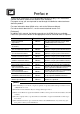
Preface UG Series Thank you for selecting the Fuji Programmable Operation Display, POD UG520/420/ 320/221/220 Series (called as the UG20 or POD, hereafter). For proper set-up, you are requested to read through this booklet to understand more about the product. For more information about UG20 series, refer to the Reference Manual. For further details about the PLC, see the manual attached to each PLC. [Reference] In addition to this manual, the following manuals on the UG20 Series are available.
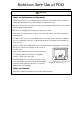
Notes on Safe Use of POD In this manual, you will find various notes categorized under the following levels with the signal words "DANGER," and "CAUTION." DANGER CAUTION Indicates an imminently hazardous situation which, if not avoided, will result in death or serious injury. Indicates a potentially hazardous situation which, if not avoided, may result in minor or moderate injury and could cause property damage.
Notes on Safe Use of POD CAUTION [Notes on System Design] • Never bundle control cables and input/output cables with high-voltage and large-current carrying cables such as power supply cables. Keep these cables at least 200 mm away from the power supply or high-voltage cables. Otherwise, malfunction may occur due to noise. • For use in a nuclear energy facility, or other facility of such official importance, please consult your local distributor.
Notes on Safe Use of POD CAUTION [Notes on Maintenance and Operation] • Fuji Electric Co., Ltd. is not responsible for any damages resulting from repair, overhaul or modification of POD that was performed by an unauthorized person. • Do not use thinners for cleaning because they may discolor the POD surface. Use alcohol or benzine commercially available. • Do not use a sharp-pointed tool when pressing a touch switch.
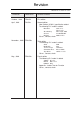
Revision *Manual No. is shown on cover. *Manual No. Revision contents October , 1999 FEH352 First edition April , 2001 FH352a Second edition New Product (UG221) specification added. The following PLC model is added. Printed on Mitsubishi Allen-Bradley Siemens Modicon QnH series FX1S series Micro Logix 1000 S7-300/400 MPI Modbus RTU Others , contents check November , 2002 FEH352b Third edition The following PLC model is added.
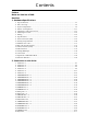
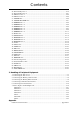
Contents Preface Notes on Safe Use of POD Revision 1. Hardware Specifications 1. Special Features .......................................................................................................... 1-1 2. Notes on Usage ............................................................................................................ 1-2 3. System Composition .................................................................................................... 1-4 4. Names of Components ......................
Contents 26. Allen-Bradley PLC • 1 ................................................................................................. 2-75 27. Allen-Bradley PLC • 2 ................................................................................................. 2-80 28. GE Fanuc PLC • 1 ...................................................................................................... 2-84 29. GE Fanuc PLC • 2 ...............................................................................................
Hardware Specifications 1. Special Features 2. Notes on Usage 3. System Composition 4. Names of Components 5. Dimensions and Panel Cut-out 6. Mounting Procedure 7. Wiring 8. Specifications 9. Serial Connector (CN1) 10. Setting of Dip Switches 11. Modular Jack 1 & 2 12. Bar Code Reader Interface 13. Printer Interface (CN2) 14. Video Interface 15. Analog RGB Input 16. Connection 17. Operation of POD Main Menu 18.
1 Special Features 1 1-1 Special Features 1) 128-color Display 128-color display which makes colorful expression possible is realized. Not only drawings but also bitmap files are clearly displayed. (UG221 and UG220 is 16-color display.) 2) Data Sheet Printing Function It is possible to make the original data sheet screen by the panel editor (= the editing software). Daily reports or monthly reports that the operator must fill out can be printed in an instant.
1-2 2 2 Notes on Usage Notes on Usage Environmental Limits 1. Use POD at an ambient temperature of 0 to 50ºC, and a relative humidity of 35-85 %RH. (But, a UG420 STN multi-color display can be used at 0 to 40ºC.) 5. Never install POD in a place where impacts or vibrations may be transmitted. 0 to 50°C 50 40 30 20 10 0 2. Install a forced fan or an air conditioner to maintain the ambient temperature when it is higher than the above mentioned range. 6.
2 Notes on Usage 3. Never install POD in the same compartment as high-voltage equipment. The unit should be at least 200 mm away from high-voltage lines or power cables. 1-3 4. Securely fasten and lock every connector for each cable. Double-check this before turning the power on. k! Loc Usage 1. An emergency stop circuit must be composed of an external relay circuit with a start signal for POD built in. Do not create switches on POD to be used in case of emergency. 5.
3 System Composition 1-4 3 System Composition System Composition / Model Indication / Peripheral Equipment System Composition The following illustration shows possible system configurations using UG20.
3 System Composition List of Models The characters on the right of model names represent optional features and special specifications. UG220H Power requirements 4 : 24V DC Main unit Interface specifications C : Serial (Link Unit Communication) (Other interfaces can be supported using the I/F unit.
1-6 3 System Composition UG420H Main unit Image input NONE 1 : Video interface (TFT color LCD Only) 2 : RGB interface (TFT VGA only) Memory card None : Standard (Outside recorder) M : Memory card interface Power requirements 1 : 100 to 200V AC 4 : 24V DC Interface specifications C : Serial (Link Unit Communication) (Other interfaces can be supported using the I/F unit.
3 System Composition 1-7 List of Options Type Optional by Manufacturer Item Card Interface UG221 UG320 UG420H-S UG420H-T UG420H-V UG520H-V Video Interface Analog RGB Input Interface Extension I/O Unit : UG00P-U1 *2 (16 inputs / 16 outputs) Serial Extension I/O : UG00P-U2 (16 inputs / 16 outputs) *2 Extension Memory Cassette: (4Mbyte) Optional by User UG220 *1 SRAM Cassette : (512Kbyte) UG00P-D4 UG221P-D4 UG00P-SR UG221P-SR Communication Interface Unit : UG03I-S/J/T/C/E/P Communication Interfac
1-8 3 System Composition Model Indication UG221, UG220 Display area : 115.2 (A 5.7 inch display.) 86.4 mm UG320 Display area : 157.4 (A 7.7 inch display.) 118.1 mm UG420 Display area : 211.2 (A 10.4 inch display.) 158.4 mm UG520 Display area : 246.0 (A 12.1 inch display.) 184.5 mm Peripheral Equipment The following options are available for using UGx20 series more effectively. UG00S-CWV3 (Panel Editor for Windows98/NT4.0/Me/2000/XP) Application software for editing display data for UG series.
3 System Composition 1-9 F R O M 1 • UG00P-D4 : for UG520, UG420, UG320 • UG221P-D4 : for UG221 Extension print circuit board to extend the memory for display data back-up. There is 4Mbyte type.
3 System Composition 1 - 10 UG03I-x [x:T T-Link, x:J OPCN-1, x:S SX BUS, x:E(2) Ethernet•FL-net, x:C CC-Link, x:P PROFIBUS] (Communication Interface Unit) Used to communicate with each network. It makes it possible to connect multiple UGx20 series to a PLC. This system, which enables other devices to connect to the same network, brings about the reduction in costs of the whole system.
4 Names of Components 4 1 - 11 Names of Components Front Side of UG220 Rear Side of UG220 10 1 13 DC24V 3 (+) (-) 5 CN2 4 MJ2 CN1 8 MJ1 9 7 2 1 Front Side of UG221 Rear Side of UG221 10 1 8 24VDC 9 3 11 5 MJ2 7 MJ1 CN1 CN2 2 6 4 1 Front Side of UG320 Rear Side of UG320 10 1 13 5 (+) DC24V (-) MJ2 MJ1 4 CN1 3 8 9 CN2 11 7 2 1 1 Mounting holes for fixtures 8 2 9 6 Display Function keys (Refer to P1-59) Power lamp DC power supply CN1: for PLC (RS-232C, RS-422
1 - 12 4 Names of Components Front Side of UG420 Rear Side of UG420 1 6 11 L 100240VAC N NC 3 12 15 13 CN1 8 MJ2 MJ1 14 CN2 7 2 1 10 9 4 Front Side of UG520 Rear Side of UG520 1 11 6 L 100240VAC N NC 12 15 13 CN1 8 MJ2 MJ1 14 CN2 7 2 1 9 10 3 4 1 2 3 4 5 6 7 8 Mounting holes for fixtures Display Function keys (Refer to P1-59) Power lamp AC power supply / DC power supply CN1: for PLC (RS-232C, RS-422) CN2: for printer Dip switches 9 MJ1, 2: for data transfer, for temperatu
5 Dimensions and Panel Cut-out 5 1 - 13 Dimensions and Panel Cut-out Dimensions of UG220 Unit : mm Rear View Top View 5 45 173.6 CN1 CN2 MJ2 Side View 130.8 88.4 138.8 Front View MJ1 117.2 182.5 Panel Cut-out of UG220 Unit : mm +0.5 -0 131 +0.
5 Dimensions and Panel Cut-out 1 - 14 Dimensions of UG221 Unit : mm Side View Front View SYSTEM F1 F3 POWER 138.8 130.8 F2 F4 F5 182.5 Under View 6 Rear View + 24V DC 4 47.3 - Do not remove this seal. unless the optional unit is mounted. MJ2 MJ1 CN2 CN1 Panel Cut-out of UG221 Unit : mm 174 + 131 +-00.5 0.
5 Dimensions and Panel Cut-out 1 - 15 Dimensions of UG320 Unit : mm Top View Rear View 220 TB1 (+) DC 24V 60.1 ( ) CN1 6 MJ2 CN2 Front View 165 175 121 Side View 160 230 Panel Cut-out of UG320 Unit : mm +0.5 -0 +0.5 -0 165.5 220.
1 - 16 5 Dimensions and Panel Cut-out Dimensions of UG420 Unit : mm Rear View Top View 288 L 100240VAC N CN1 16 76.3 NC MJ2 CN2 Front View 215.2 240 158 Side View 211 310 Panel Cut-out of UG420 Unit : mm +0.5 -0 +0.5 -0 216.
5 Dimensions and Panel Cut-out 1 - 17 Dimensions of UG520 Unit : mm Top View Rear View 312 L 100240VAC NC CN1 16 79.8 N MJ2 CN2 Side View 245.2 270 185 Front View 247 334 Panel Cut-out of UG520 Unit : mm +0.5 -0 +0.5 -0 246.
6 Mounting Procedure 1 - 18 6 Mounting Procedure Mounting Procedure 1 Cut out the mounting panel (Max. thick: 3.2 mm) to match the dimensions shown below. Mounting panel Unit : mm 174 220.5 +0.5 -0 +0.5 -0 Cut-out UG320 +0.5 -0 313 +0.5 -0 246.2 216.2 +0.5 -0 +0.5 -0 165.5 -+0.5 0 UG420 2 165.5 +0.5 -0 UG220 UG221 289 +0.5 -0 +0.5 -0 131 220.5 UG520 Insert the fixtures attached to UGx20 into the mounting holes on UGx20. Tighten them with the locking screws.
7 Wiring 7 1 - 19 Wiring Caution • • Do not remove the dust-proof seal till you finish wiring in the panel. If the seal is removed, conductor chips or other foreign matter may enter the device to cause failure. When you finished wiring in the panel, be sure to remove the dust-proof seal. Electrical Wiring Connects the cable for power supply to TB1 on the rear side of UGx20.
1 - 20 7 Wiring Grounding This equipment must be earthed. UGx20 other equipment An independent earth pole shall be used for POD. (The level of grounding resistance should be less than 100 Ω.) Use a cable which has a nominal cross section of more than 2mm2 for grounding. Grounding point shall be near the POD to shorten the Grounding resistance : less than 100Ω distance of grounding wires. Wiring for Communication Never place the communication cable with electric circuits.
8 Specifications 8 1 - 21 Specifications General Specifications Type UG221 UG220 Item Rated Voltage 24V DC 24V ± 10% DC Power Supply Permissible Range of Voltage 10ms or less Permissible Momentary Power Failure Demand Physical Environment 10W or less 20W or less 15A 1ms 15A 1.5ms Rushed Electric Current With-stand voltage DC external terminals to FG : 500V AC per min.
1 - 22 8 Specifications UG420 Type AC Power Supply Item Rated Voltage Power Supply Permissible Range of Voltage Permissible Momentary Power Failure Demand Rushed Electric Current UG520 DC Power Supply AC PowerSupply DC Power Supply 100/240V AC 24V DC 100/240V AC 24V DC 85 to 265V AC 24V ± 10% DC 85 to 265V AC 24V ± 10% DC (47 to 440Hz) (47 to 440Hz) 20ms or less 10ms or less 20ms or less 10ms or less 45VA or less 25W or less 50VA or less 25W or less 20A : 100V AC 30A 20A : 10
8 Specifications 1 - 23 Display Specifications Type UG220H-L Item Display Device Resolution W Dot Pitch W UG220H-S UG221H-L UG221H-T UG320H STN STN STN TFT STN Monochrome Color Monochrome Color Color LCD LCD LCD Color LCD LCD H (dots) H (mm) UG221H-S STN 0.36 0.36 0.12 0.36 320 240 0.36 0.36 0.12 Effective Display Area 115.2 W (5.7 inches) H (mm) LCD 640 0.36 0.36 480 0.36 0.082 0.246 157.4 86.4 118.1 (7.
1 - 24 8 Specifications Display Function Specifications (All the UGx20 series) Item Specifications Display Language Japanese Eng./W.
8 Specifications 1 - 25 Function Performance Specifications (All the UGx20 series) Specifications Item Screens Max. 1024 Screen Memory FP-ROM (flash memory), Appox. 2,816Kbytes* (different from the language) Switches 768 per screen (192 per screen for UG221/220 : However, the number of memory settings is limited.
8 Specifications 1 - 26 Touch Panel Specifications (All the UGx20 series) Item Specifications Switch Resolution Analog, 1024(W) 1024(H) Matrix type, UG221: 20(W) 12(H) pcs Form Resistance film form Life of Touch Panel Use of one million times or more Function Switch Specifications (All the UGx20 series) Item Specifications Number of Switches 8 (6 for UG221/UG220) Type of Switch Pressure sensitive switches Life of Switch Use of one million times or more Interface Specifications (All the
9 Serial Connector (CN1) 9 1 - 27 Serial Connector (CN1) CN1 is used for communicating between a PLC and a POD(RS-232C, RS-422/485). Serial Connector (CN1) The pin arrangement of serial connector is as follows: L 100240VAC N NC ) CN1 CN1 (Dsub 25pin MJ2 1 MJ1 CN2 Signal 1 FG Frame ground 2 SD RS-232C send data 3 RD RS-232C receive data 4 RS RS-232C RS request to send 5 CS RS-232C CS clear to send SG Signal ground Not used 6 14 7 8 13 Contents Pin No.
1 - 28 9 Serial Connector (CN1) RS-422 In case of RS-422, +SD and -SD, and +RD and -RD form a pair. Use SG if possible. Connect the shielded cable to pin No. 1 or the connector case cover. Use UG00P-TC which is the optional equipment made by Fuji Electric. Co., Ltd. in case of using terminal blocks in RS-422/485 connection. Specify terminal resistance by the dip switches on POD. (Refer to the next page.) POD (CN1) Signal Pin No.
10 Setting of Dip Switches 10 1 - 29 Setting of Dip Switches Setting of Dip Switches (DIPSW) ON 1 Memory Extension 2 (invalid for UG220) 2 3 4 5 6 Not used 7 8 Terminal resistance of MJ2(modular jack 2) But, it depends on a hardware version. RD terminal resistance of pin No. 24 and 25 Terminal resistance of MJ1(modular jack 1) Keep DIPSW 2, 3, 4 and 5 (not used) OFF. Setting of Memory Extension 2 (This dip switch is invalid for UG220. Keep DIPSW 1 OFF.
1 - 30 11 Modular Jack 1 & 2 11 Modular Jack 1 & 2 Modular Jack 1 & 2 (MJ1/2) The right diagram is the pin arrangement and the signal name of modular jack 1 & 2. MJ1/2 12345678 Pin No. 1 2 3 4 5 6 7 8 Signal +SD/RD -SD/RD +5V +5V 0V 0V RD SD Contents RS-485 + data RS-485 - data Output power supply Max. 150mA Signal ground RS-232C receive data RS-232C send data Setting of Modular Jack 1 & 2 (MJ1/MJ2) Specify the use of MJ1/MJ2 by the software (UG00S-CW). Select [Modular...] from [System Setting].
12 Bar Code Reader Interface 12 1 - 31 Bar Code Reader Interface It is possible to receive the signal from a bar code reader by connecting a bar code reader to POD via the modular jack (MJ1/MJ2) of POD series. 12345678 To connect a bar code reader to POD via MJ1/MJ2, use the cable which is the optional equipment made by Fuji Electric. Co., Ltd. (UG00C-B).
1 - 32 13 Printer Interface (CN2) 13 Printer Interface (CN2) When a printer is connected to POD via the connector (CN2), it is possible to hard-copy the screen display of POD, the data sheet, or the sampling data. To connect a printer to POD, use the parallel interface cable of 36 pins which is optional equipment made by Fuji Electric. Co., Ltd. (UG00C-C). When using CBM292/293 printer, our printer cable be (UG00C-A) is available.
14 Video Interface 14 1 - 33 Video Interface (Option: UG520/UG420 only) When a video or a CCD camera is connected to the optional UGx20 which has a video interface, the image which is taken by a video or a camera is displayed directly in a screen of UGx20 series (only in case of UG520H-V and UG420H-T/V).
1 - 34 15 Analog RGB Input 15 Analog RGB Input (Option: UG420H-T only) When connector CN3 of UG420H-TC (analog RGB input adapted product) is connected to a personal computer, the screen image of the personal computer can be displayed on the UG420H-TC.
15 Analog RGB Input 1 - 35 Touch-switch emulation function With this function, you can manipulate the Windows screen displayed on the POD with touch switches, i.e. without using the mouse. Applicable version of screen development editor This function is adapted to 2.4.0.0 or newer versions of the screen development editor. Applicable version of POD system program This function is adapted to 1.200 or newer versions of POD system program (SYSTEM PROG.VER.) Touch panel driver to be installed PN-WIN98/95 Ver.
1 - 36 15 Analog RGB Input 4. Save the file, and send it to the POD. 5. Mode is changed to RUN. In this mode, change screen over to the [RGB Input] screen. (Windows screen is displayed.) DOS/V Personal POD computer 6. In order to execute “touch-panel emulation”, UG00C-T Editor Port MJ1 COM1 connect between COM1 (communication port) of MJ2 the personal computer and MJ2 (touch switch) COM2 Touch Switch of the POD by means of UG00C-T. 7.
16 Connection 16 1 - 37 Connection 1 : 1 Link Communication One POD and one PLC are connected. PLC POD run stop RS-232C or RS-422(RS-485) 1 : n Link Communication (Multi-drop) One POD and multiple PLCs are connected.
1 - 38 15 Connection Multi-drop Communication (RS-485) Refer to the PLC manual of each manufacturer for connection. The following example describes how one POD is connected to three PLCs made by MITSUBISHI. See MITSUBISHI’s manual for further details. POD (CN1) Link unit Link unit Link unit Signal Pin No.
16 Connection FUJI : MICREX-F series Depends on the model FUJI : MICREX-SX series Provided FUJI : MICREX-SX CPU Provided FUJI : FLEX-PC series Depends on the model FUJI : FLEX-PC CPU Depends on the model FUJI : FLEX-PC COM(T) Provided FUJI : FLEX-PC(T) Depends on the model FUJI : FLEX-PC CPU(T) Depends on the model MITSUBISHI : AnA/N/U series Provided MITSUBISHI : QnA series Provided MITSUBISHI : ACPU Port Provided MITSUBISHI : FX series Depends on the model MITSUBISHI : QnACPU Port Provi
16 Connection 1 - 40 n : 1 Link Communication (Multi-link) Multiple POD and a PLC are connected. (n=1 to 32) POD 1 POD 3 POD 2 POD n * The connections shown below are not recommended.
16 Connection 1 - 41 When multiple POD are connected to a link unit of PLC, use the terminal converter (UG00P-TC), the optional equipment made by Fuji Electric. Co., Ltd. for RS-485 connection. Set the dip switch (SW1) of UG00P-TC as 2-wire connection when the UG00P-TC terminal converter is used.
1 - 42 17 Operation of POD Main Menu 17 Operation of POD Main Menu When the power of POD is turned on for the first time, the screen on the below left is displayed. After transferring the screen data to POD, the following “Main Menu” is displayed. When power is turned on for the first time: "Main Menu" after trasferring data UG420H-TC1M1 Main Menu System Information SYSTEM PROG. VER.1.000 Screen Data Information Size : 786432 1998- 9- 1 FONT VER.1.000/1.000/1.
17 Operation of POD Main Menu System program version 1 - 43 Model name of POD Font data version Data size UG420H-TC1M1 Main Menu System Information SYSTEM PROG. VER.1.000 Screen Data Information Size : PLC type and comment specified by the panel editor 786432 1998- 9- 1 FONT VER.1.000/1.000/1.000 JAPANESE 32 Connection: 1 : 1 Signal Level: RS232C PLC Stat.No.: 0 Own Stat.No.: 1 V6 Total: 2 Retry: 10 PLC I/F driver version and name Error: Stop Time-Out: 0.
17 Operation of POD Main Menu 1 - 44 I/O Test When the switch “a” on the “Main Menu” is pressed, the following “I/O Test” is displayed. This is the test menu to check only POD hardware. Memory-Card I/O Test B E C Press the [I/O Test] switch. D I/O Test Main Menu SYS F-1 Printer Check Switch Check F-2 A F-3 Self-Loop Test Please refer to the manual, "Hardware Specifications".
17 Operation of POD Main Menu 1 - 45 A. Self-loop Test This is the test menu to check the signals necessary for UG20 to communicate with PLC or a personal computer by using only POD. Signal Test of RS-232C in CN1 Select [CN1] and [RS-232C] in [Communication Port] by pressing each switch. Communication Port CN1 RS-232C MJ1 RS-485 MJ2 •Loop-back Test Check the signals, [SD] and [RD]. 1 Jump pins, 2 and 3 of CN1. 2 The test is OK, if the [OK] lamp turns on when the [Self-Loop Test] switch is pressed.
1 - 46 17 Operation of POD Main Menu Signal Test of RS-485 in CN1 Select [CN1] and [RS-485] in [Communication Port] by pressing each switch. Communication Port CN1 RS-232C MJ1 RS-485 MJ2 •Loop-back Test Check the signals, [SD] and [RD]. 1 2 Jump each pin, 12 and 24, 13 and 25 of CN1. The test is OK, if the [OK] lamp turns on when the [Self-Loop Test] switch is pressed.
17 Operation of POD Main Menu 1 - 47 Signal Test of RS-232C in MJ1 and MJ2 Select [MJ1] (or [MJ2]) and [RS-232C] in [Communication Port] by pressing each switch. Communication Port CN1 RS-232C MJ1 RS-485 MJ2 •Loop-back Test Check the signals, [SD] and [RD]. Execute the test by connecting the data transfer cable (UG00C-T) to CN1. 1. Set the adaptor, ADP25-9, which is attached to UG00C-T, to UG00C-T. And connect the modular jack side of UG00C-T to MJ1 (or MJ2), ADP25-9 side of UG00C-T to CN1.
17 Operation of POD Main Menu 1 - 48 B. Printer Check Check the signal of printer. The test is OK if the test printout is executed satisfactorily when connecting POD to a printer and pressing this [Printer Check] switch. !"#$%&@ !"#$%&@ !"#$%&@ !"#$%&@ !"#$%&@ !"#$%&@ !"#$%&@ 0123456789 0123456789 0123456789 0123456789 0123456789 0123456789 0123456789 ABCDEFGHIJKLMNO ABCDEFGHIJKLMNO ABCDEFGHIJKLMNO ABCDEFGHIJKLMNO ABCDEFGHIJKLMNO ABCDEFGHIJKLMNO ABCDEFGHIJKLMNO C.
17 Operation of POD Main Menu * 1 - 49 In case of matrix type When pressing the [Switch Check] switch, the following screen which is divided by a minimum size of switch is displayed. Confirm that the color of the pressed switch changes into white. Pressing the corner right below leads to the previous [I/O Test] screen. the [Switch Check] screen Main Menu SYS F-1 Switch Check F-2 If the pressed area is reversed, these switches reacts to the touch normally. Press the [Switch Check] switch. D.
1 - 50 17 Operation of POD Main Menu Memory-Card When the [Memory-Card] switch on the “Main Menu” is pressed, the following “Memory-Card” is displayed. This screen is to transfer the screen data between POD and a memory-card. Memory-Card I/O Test The "Memory-Card" screen is displayed. Press the [Memory-Card] switch.
17 Operation of POD Main Menu 1 - 51 2)Data Selection, Transfer Pressing each switch leads to selection of the target for data transferring. (Possible to select multiple items.) Data Selection Transfer Memory-Card Memory-Card Main Menu Memory-Card Information Close Main Menu Close Memory-Card Information Port Selection Port Selection Sys Program : Modular Jack Memory-Card Version:-.--MJ1 Socket Font Data : Version:-.---/-.---/-.--I/F Driver : Version:-.
1 - 52 17 Operation of POD Main Menu Message Display in Data Transferring If an error occurs during transferring data, the message display window shown on the right is displayed. The kinds and the contents of the messages are as shown below. Message Work nomally finished. OK Contents Work normally finished. The specified operation has been concluded normally. UG00P-MR not connecting UG00P-MR is not connecting when selecting a modular jack.
17 Operation of POD Main Menu 1 - 53 Screen Adjustment [Option: UG420H-T(RGB input adapted product) only] Depending on what type of personal computer is used, RGB output frequency for Windows screen, BIOS screen or DOS screen changes. Therefore, adjustment is necessary. When there is only one type of output frequency, select either “Setting 1” or “Setting 2”. How to adjust 1. Display the local MAIN MENU screen. Main Menu UG420H-TC12 System Information SYSTEM PROG. VER. 1.150 1998-5 -5 FONT VER.1.
1 - 54 3. 17 Operation of POD Main Menu First, BIOS screen is adjusted. Press the [Adjust] switch in the [Setting 1] box to activate RGB display mode. RGB Adjust Main Menu Please refer to the manual, "Hardware". Horizontal : 31180 Hz Vertical : 59 Hz Setting-1 Setting-2 Not used Not used Adjust Adjust Clear Save With the BIOS screen displayed, adjust with switches [F • 1] to [F • 6]. [SYSTEM] End of adjustment [F • 1] Vertical: Screen is moved downward.
17 Operation of POD Main Menu 4. 1 - 55 Then the Windows screen is adjusted. Press the [Adjust] switch in the [Setting 2] box to activate RGB display mode. RGB Adjust Main Menu Please refer to the manual, "Hardware". Horizontal : 31180 Hz Vertical : 59 Hz Setting-1 Setting-2 Not used Not used Adjust Adjust Clear Save With the Windows screen displayed, adjust with switches [F • 1] to [F • 6]. When adjustment is completed, press the [SYSTEM] switch to return to the [RGB Adjust] screen.
1 - 56 5. 17 Operation of POD Main Menu Press the [Save] switch to save the setting data. (The setting data is written in the flash ROM.) RGB Adjust Main Menu Please refer to the manual, "Hardware". Horizontal : 31180 Hz Setting-2 Not used Not used Adjust Adjust Clear 6. Vertical : 59 Hz Setting-1 Save By doing this, screen adjustment is completed. Notes on RGB input When there is no RGB input (when the cable is not connected), the mode cannot be changed over to RGB display mode.
17 Operation of POD Main Menu 1 - 57 Setting for SRAM cassette When the optional SRAM cassette (UG00P-SR, UG221P-SR) is installed in the POD main unit, it is possible to adjust the internal calendar of the SRAM cassette or to format the SRAM cassette. Adjusting the internal calendar of SRAM cassette (Main Menu) 1)Activate the [Main Menu] screen. Main Menu UG420H-TC12 System Information SYSTEM PROG. VER. 1.150 1998-5 -5 FONT VER.1.100/1.090/1.
1 - 58 18 Function Switches Formatting the SRAM cassette When you changed the setting of SRAM cassette area, be sure to format the SRAM cassette. SRAM cassette can be formatted from the [Main Menu] screen. If the format of the SRAM cassette does not coincide with the setting of screen data, the SRAM cassette cannot be used (error No. 163 occurs.) How to format the SRAM cassette 1)Activate the [Main Menu] screen. • Main Menu UG420H-TC12 System Information SYSTEM PROG. VER. 1.150 1998-5 -5 FONT VER.1.
17 Operation of POD Main Menu 18 1 - 59 Function Switches Type [SYSTEM], [F1], [F2], [F3], [F4], [F5], [F6], [F7] (UG221, UG220 : [SYSTEM], [F1] ~ [F5]) the [SYSTEM] switch By pressing this switch, the functions of the switches [F1] ~ [F7] are defined. The type of the [SYSTEM] switch is alternate. When this switch is pressed once, the switch menu is displayed by the side of the function switches [F1] ~ [F5], and each function switch corresponds to an item on the displayed switch menu.
Connection to Link Units 1. FUJI PLC • 1 2. FUJI PLC • 2 3. FUJI PLC • 3 4. FUJI PLC • 4 5. FUJI PLC • 5 6. FUJI PLC • 6 7. MITSUBISHI PLC • 1 8. MITSUBISHI PLC • 2 9. MITSUBISHI PLC • 3 10. MITSUBISHI PLC • 4 11. MITSUBISHI PLC • 5 12. MITSUBISHI PLC • 6 13. OMRON PLC• 1 14. OMRON PLC• 2 15. Sharp PLC • 1 16. Sharp PLC • 2 17. HITACHI PLC • 1 18. HITACHI PLC • 2 19. Matsushita PLC 20. YOKOGAWA PLC • 1 21. YOKOGAWA PLC • 2 22. YASKAWA PLC•1 23. YASKAWA PLC•2 24. TOYOPUC PLC 25. Koyo PLC 26.
1 FUJI PLC • 1 1 2-1 FUJI PLC • 1 (MICREX-F series) Available PLC PLC Select PLC Type Link Unit F55 F70, F70S MICREX-F Series F80H, F120H, F120S F140S, F15xS Wiring Diagram NV1L-RS2 RS-232C [Wiring Diagram 1] NC1L-RS2 RS-232C [Wiring Diagram 1] NC1L-RS4 RS-485 [Wiring Diagram 2] FFU120B FFK120A RS-232C [Wiring Diagram 1] RS-485 [Wiring Diagram 2] Communication Setting The recommended communication parameter setting of both PLC and POD is as follows: Item Setting of PLC Comm.
2-2 1 FUJI PLC • 1 Available Memory Memory *1 • *2 • • • 0 Remarks (auxiliary relay) K (keep relay) 1 WK as word device B (input/output relay) 2 WB as word device L (link relay) 9 WL as word device F (special relay) 10 WF as word device (Read only) TS (timer/set value) 11 TR (timer/current value) 12 *1 *1 *1 *1 *1 *1 *2 *3 W9 (timer/current value 0.
1 FUJI PLC • 1 *3 • 2-3 When you access the file memory from the POD, be sure to define FILE instruction on the PLC side. File type must be SI (16-bit length). Communication with file memories that are defined by BD, DI, etc. cannot correctly be performed. To specify a memory from the editor, input [File No.] + [ : ] (colon) + [address] in this order. [Example] To specify W30.2 W30 : 00002 Address Colon File No. Set the memory to the extent of the memory range of each PLC model.
2-4 1 FUJI PLC • 2 2 FUJI PLC • 2 (MICREX-SX series) Available PLC Select PLC Type MICREX-SX Series * PLC Wiring Diagram Link Unit SPH Series (NP1PS- x ) NP1L-RS1 RS-232C [Wiring Diagram 1] RS-485 [Wiring Diagram 2] NP1L-RS2 RS-232C [Wiring Diagram 1] NP1L-RS4 RS-485 [Wiring Diagram 2] Only one unit of POD can be connected to one link unit, except for “Multi-link 2” connection.
2 FUJI PLC • 2 2-5 Wiring The following is a diagram to show the wiring of the cable which connects POD to PLC. RS-232C Wiring Diagram 1 POD (CN1) D-sub 25pin(Male: ) PLC FG 1 SD 2 RD 2 RD 3 SD 3 RS 4 ER 4 CS 5 SG 5 SG 7 DR 6 RS 7 CS 8 D-sub 9pin(Male: *Use twist shielded cables.
2-6 2 FUJI PLC • 3 3 FUJI PLC • 3 (MICREX-SX CPU Port) Available PLC Select PLC Type PLC Connected Cable MICREX-SX MICREX-SX Loader Port CPU * UG00C-Sx When the CPU is updated, or the specifications are changed, there is some possibility that POD cannot be connected to the PLC. Communication Setting Connect to the CPU port. The communication parameter setting of POD is done automatically. Item Setting of PLC Comm.
3 FUJI PLC • 3 2-7 Notes on the direct connection with the CPU port of SX series CPU • • • Fully consider the influence of noise on the communication cable routed between the POD and MICREX-SX. (The level of noise resistance when a ferrite core is attached to the cable: 1,000 V) Fully consider the influence of noise on the cable when routing it on the board and in the unit. Route the cable apart from the power lines. The longer the communication cable, the more it is influenced by noise.
2-8 3 FUJI PLC • 4 4 FUJI PLC • 4 (FLEX-PC series) Available PLC PLC Select PLC Type *1 Link Unit NS Series, NS-T NS-RS1 Wiring Diagram RS-232C [Wiring Diagram 1] RS-485 [Wiring Diagram 2] FLEX-PC Series NJ Series, NJ-T NB Series *1 NJ-RS2 RS-232C [Wiring Diagram 1] NJ-RS4 RS-485 [Wiring Diagram 2] NB-RS1 RS-232C [Wiring Diagram 1] RS-485 [Wiring Diagram 2] When FLEX-PC TOYOTA version is used, select “FLEX-PC(T)” in [PLC Type].
4 FUJI PLC • 4 Switch Setting MODE Switch: RS-232C: 1 RS-485: 3 RS-485 Port Setting SW: “0” for both 10, RS-485 Terminal Resistor: ON Character Switches 1 No Setting 8 ON Switch setting 7 ON Parity provided 6 ON Even 5 ON 7 bit 4 ON 1 bit 3 ON 2 ON 1 OFF Contents Same as POD (normally 19200bps) Available Memory Standard Memory TOYOTA Ver.
2 - 10 4 FUJI PLC • 4 Wiring The following is a diagram to show the wiring of the cable which connects POD to PLC. RS-232C Wiring Diagram 1 POD (CN1) D-sub 25pin(Male: ) PLC FG 1 SD 2 SD 2 RD 3 RD 3 RS 4 RS 4 CS 5 CS 5 SG 7 DR 6 SG 7 CD 8 D-sub 25pin(Male: *Use twist shielded cables. RS-485 Wiring Diagram 2 POD (CN1) D-sub 25pin(Male: ) FG 1 PLC SG 7 SDA +SD 12 SDB -SD 13 RDA +RD 24 RDB -RD 25 SG *Use twist shielded cables.
4 FUJI PLC • 5 5 2 - 11 FUJI PLC • 5 (FLEX-PC CPU port) Available PLC *1 Select PLC Type PLC *1 FLEX-PC CPU FLEX-PC Loader Port RS-422 [UG200C-N] NJ-B16 RS-232C Port RS-232C [Wiring Diagram 1] Wiring Diagram When FLEX-PC CPU TOYOTA version is used, select “FLEX-PC CPU(T)” in [PLC Type]. When the CPU is updated, or the specifications are changed, there is some possibility that POD cannot be connected to the PLC. Communication Setting Connect to the CPU port.
2 - 12 5 FUJI PLC • 5 Wiring • • • Fully consider the influence of noise on the communication cable routed between the POD and FLEX-PC. (The level of noise resistance when a ferrite core is attached to the cable: 1,000 V) Fully consider the influence of noise on the cable when routing it on the board and in the unit. Route the cable apart from the power lines. The longer the communication cable, the more it is influenced by noise. Carefully route the cable.
5 FUJI PLC • 5 Wiring The following is a diagram to show the wiring of the cable which connects POD to PLC. RS-422 Wiring Diagram 1 ( connection of the UG200C-N ) POD (CN1) D-sub 25pin(Male: ) FG 1 PLC +RD 24 3 +SD 12 5 SG 7 2 -RD 25 4 -SD 13 6 8 8 *Use twist shielded cables. RS-232C Wiring Diagram 2 POD (CN1) D-sub 25pin (Male: PLC (NJ-B16) ) FG 1 SD 2 RD 2 RD 3 SD 3 RS 4 CTS 4 CS 5 RTS 5 SG 7 SG 7 D-sub 15pin (Male: *Use twist shielded cables.
2 - 14 5 FUJI PLC • 6 6 FUJI PLC • 6 (TOYOTA version NJ Computer Link) Available PLC Select PLC Type FLEX-PC COM Wiring Diagram PLC Computer link of FLEX-PC NJ-JM RS-422 [Wiring Diagram 1] Connect to the terminal block of the NJ-JM computer link. For further information, refer to the PLC manual.
6 FUJI PLC • 6 Available Memory Memory TYPE Remarks D (data register) R (link register) 0 1 M (internal relay) 2 K (latch relay) 3 WK as word device X (input relay) 4 WX as word device Y (output relay) 5 WY as word device W (file register) 6 TN (timer/current value) 7 Read only 8 Read only CN (counter/current value) T (timer/contact) 9 C (counter/contact) 10 Z (special register) 12 V (special relay) 13 WM as word device * * WV as word device The current values
2 - 16 7 7 MITSUBISHI PLC • 1 MITSUBISHI PLC • 1 (A/Q series link unit) Available PLC Select PLC Type PLC A2A, A3A AJ71C24-S6 AJ71C24-S8 AJ71UC24 A2U, A3U, A4U AJ71UC24 A1, A2, A3 A1N, A2N, A3N A3H, A3M, A73 AJ71C24 AJ71C24-S3 AJ71C24-S6 AJ71C24-S8 AJ71UC24 A0J2, A0J2H A0J2C214-S1 A series link A2US A1S, A1SJ, A2S A2CCPUC24 QnH(A mode) QnA series link Q2A, Q3A, Q4A Q2ASx QnH(Q mode) QnH(Q) series link Link Unit Q00, Q01, Q00J Q00, Q01 Wiring Diagram RS-232C [Wiring Diagram 2] RS-422 [
7 MITSUBISHI PLC • 1 2 - 17 Communication Setting The recommended communication parameter setting of both PLC and POD is as follows: A series link unit Item Setting of PLC Baud Rate 19200bps Port 0 for both STATION x10 and x1 0 Parity Even Even Comm. Parameter of POD 19200bps *1 Transmission Control Mode RS-232C MODE1 Trans. Mode 1 RS-422 MODE5 Trans.
2 - 18 7 MITSUBISHI PLC • 1 Be sure to check these items. Check that these settings are the same as POD comm. parameters. Switch Setting The following is an example to show the settings for both rotary dip switches and dip switches on PLC. ON Signal Level: RS-232C, Baud Rate: 19200bps, Trans. Mode: Trans.
7 MITSUBISHI PLC • 1 2 - 19 Signal Level: RS-422, Baud Rate: 19200bps, Trans. Mode: Trans.
2 - 20 7 MITSUBISHI PLC • 1 Wiring The following is a diagram to show the wiring of the cable which connects POD to PLC. RS-232C Wiring Diagram 1 POD (CN1) D-sub 25pin(Male: ) PLC FG 1 SD 2 CD 1 RD 3 RD 2 RS 4 SD 3 CS 5 SG 5 SG 7 DR 6 RS 7 CS 8 D-sub 9pin(Male: *Use twist shielded cables.
7 MITSUBISHI PLC • 1 2 - 21 RS-422 Wiring Diagram 3 POD (CN1) D-sub 25pin(Male: ) FG 1 PLC SG 7 SDA +SD 12 SDB -SD 13 RDA +RD 24 RDB -RD 25 SG *Use twist shielded cables. Wiring Diagram 4 POD (CN1) D-sub 25pin(Male: ) PLC FG 1 SG 7 RDA 2 +SD 12 SDA 3 -SD 13 DSRA 4 +RD 24 DTRA 5 -RD 25 SG 7 RDB 15 SDB 16 DSRB 17 DTRB 18 D-sub 25pin(Male: 20 *Use twist shielded cables.
2 - 22 8 7 MITSUBISHI PLC • 2 MITSUBISHI PLC • 2 (A/QnA series CPU ) Connection Connect to the A/Q series CPU port. The communication parameter setting of POD is done automatically.
8 MITSUBISHI PLC • 2 2 - 23 Available Memory Memory TYPE D (data register) 0 W (link register) 1 R (file register) 2 TN (timer/current value) 3 CN (counter/current value) *2 4 SPU (special unit) 5 M (internal relay) 6 L (latch relay) 7 B (link relay) 8 X (input relay) 9 Y (output relay) 10 TS (timer/contact) 11 TC (timer/coil) 12 CS (counter/contact) 13 CC (counter/coil) 14 SD 16 (special register) Remarks Unit No.
2 - 24 8 MITSUBISHI PLC • 2 Wiring The following is a diagram to show the wiring of the cable which connects POD to PLC. (connection of the UG200C-M) RS-422 Wiring Diagram 1 POD (CN1) D-sub 25pin(Male: ) PLC FG 1 SG 7 2 +RxD +SD 12 3 +TxD -SD 13 4 +DSR +RTS 14 5 +DTR -RTS 17 7 SG -CTS 18 15 -RxD +CTS 19 16 -TxD +RD 24 17 -DSR -RD 25 18 -DTR D-sub 25pin(Male: ) 20 21 *Use twist shielded cables.
8 MITSUBISHI PLC • 2 2 - 25 Notes on using UG00P-DI (Dual Port Interface) As the UG00P-DI is powered by a CPU, check that the electric capacity of the CPU is at 5V (power consumption: max. 350mA). The distance between the CPU and the UG00P-DI should be as short as possible (max. 1 to 1.5m). For wiring, take appropriate measures to eliminate noise. Specify the value more than 150 (=1.5 sec) in [Time-out Time] of [Comm. Parameter] in case of connecting POD to a UG00P-DI. MITSUBISHI A/QnA Series.
2 - 26 9 8 MITSUBISHI PLC • 3 MITSUBISHI PLC • 3 (QnH series CPU) Connection Connect to the QnH series CPU. The communication parameter setting of POD is done automatically. Available PLC Select PLC Type PLC QnH(A) series CPU Q06H-A Q02, *1 Q02H, QnH(Q) series CPU Q06H, Q12H, Q25H Wiring Diagram RS-232C [UG00C-Q] or [Wiring Diagram 1] *1 About the ladder transfer function, refer to Appendix.
9 MITSUBISHI PLC • 3 2 - 27 Available Memory Memory TYPE D (data register) W (link register) 1 R (file register) 2 TN (timer/current value) 3 Remarks 0 CN (counter/current value) 4 SPU (special unit) 5 M (internal relay) 6 L (latch relay) 7 B (link relay) 8 X (input relay) 9 Y (output relay) 10 TS (timer/contact) 11 TC (timer/coil) 12 CS (counter/contact) 13 Unit No.
2 - 28 10 MITSUBISHI PLC • 4 10 MITSUBISHI PLC • 4 (FX / FX2N / FX1S series CPU) Connection Connect to the FX series CPU port. The communication parameter setting of POD is done automatically.
10 MITSUBISHI PLC • 4 2 - 29 Available Memory FX1/2, FX0N, FX1S series CPU Memory D (data register) TN (timer/current value) TYPE 1 CN (counter/current value) 2 32CN (counter 32bits) 3 M (internal relay) 4 S (state) 5 X (input relay) 6 Y (output relay) 7 TS (timer/contact) 8 CS (counter/contact) 9 DX (Data register) 10 *1 *2 Remarks 0 *1 Read only *2 In case of the items which can display double word data (e.g.
2 - 30 10 MITSUBISHI PLC • 4 Wiring The following is a diagram to show the wiring of the cable which connects POD to PLC. RS-232C Use the cable, “UG00C-X”(3m), made by Fuji Electric Co., Ltd. in case of RS-232C connection.
10 MITSUBISHI PLC • 4 2 - 31 Notes on using UG00P-DI (Dual Port Interface) As the UG00P-DI is powered by a CPU, check that the electric capacity of the CPU is at 5V (power consumption: max. 350mA). The distance between the CPU and the UG00P-DI should be as short as possible (max. 1 to 1.5m). For wiring, take appropriate measures to eliminate noise. Specify the value more than 150 (=1.5 s) in [Time-out Time] of [Comm. Parameter] in case of connecting POD to a UG00P-DI.
2 - 32 11 MITSUBISHI PLC • 5 11 MITSUBISHI PLC • 5 (FX series link [A prt] ) Available PLC Select PLC Type PLC FX2N FX series (A protocol) FX1N FX1S FX0N FX2NC Link Unit Wiring Diagram FX2N-232-BD RS-232C [Wiring Diagram 1] FX2N-485-BD RS-485 [Wiring Diagram 3] FX2N-422-BD RS-422 [ UG00C-E ] made by Fuji Electric FX1N-232-BD RS-232C [Wiring Diagram 1] FX1N-485-BD RS-485 [Wiring Diagram 3] FX1N-422-BD RS-422 [ UG00C-E ] made by Fuji Electric FX0N-232ADP RS-232C [Wiring Diagram 2] F
11 MITSUBISHI PLC • 5 2 - 33 Available Memory Memory *1 *2 TYPE D (data register) 0 TN (timer/current value) 1 CN (counter/current value) 2 32CN (counter 32bits) 3 M (internal relay) 4 S (state) 5 X (input relay) 6 Y (output relay) 7 TS (timer/contact) 8 CS (counter/contact) 9 Remarks *1 *2 Read only The meaning of CN200~CN255 is the same as the meaning of 32CN(counter 32bits). In case of the items which can display double word data (e.g.
2 - 34 11 MITSUBISHI PLC • 5 Wiring The following is a diagram to show the wiring of the cable which connects POD to PLC. RS-232C Wiring Diagram 1 POD (CN1) D-sub 25pin(Male: ) PLC FG 1 SD 2 RD 2 RD 3 SD 3 RS 4 SG 5 CS 5 SG 7 D-sub 9pin(Female: ) *Use twist shielded cables. Wiring Diagram 2 POD (CN1) D-sub 25pin(Male: ) PLC FG 1 SD 2 SD 2 RD 3 RD 3 RS 4 SG 7 CS 5 SG 7 D-sub 25pin(Male: *Use twist shielded cables.
12 MITSUBISHI PLC • 6 12 2 - 35 MITSUBISHI PLC • 6 (A Link + Net 10) POD can access other CPUs on the NET II(/B) or NET/10 when POD is connected to one of the link units that the data link system or network system consists of. Select “A Link + Net10” as PLC setting when configuring the screen data on the panel editor. To access other CPU on the NET II (/B) or NET/10 from POD. • In case of NET II(/B), only the network which has the CPU with the link unit connected to the POD (e.g. No. 1) can be accessed.
2 - 36 12 MITSUBISHI PLC • 6 Macro type to specify network • • • • • • • • • • • • • • • • • • • • • • • • • • • • [OUT_ENQ] command of [SYS] F1 Memory n+0 0 (fixed) n+1 Specify network: 2 (fixed) n+2 System code n+3 Network No. The addresses n+0 and n+1 are fixed for 0 and 2. Specify n+2 [System code] to 1: NET/10 2: NET II(/B) Enter “0” to n+3 [Network No.] when n+2 [System code] indicates “2”, and “the number to be accessed” to n+3 [Network No.] when n+2 [System code] indicates “1”.
13 OMRON PLC • 1 13 OMRON PLC • 1 (C/CV/CS1 series) Available PLC Select PLC Type PLC C20H, C28H, C40H C120, C120F C200H C500, C500F C1000H C2000, C2000H SYSMAC C SYSMAC CS1 RS-232C [Wiring Diagram 1] C120-LK201-V1 RS-232C [Wiring Diagram 3] C120-LK202-V1 RS-422 [Wiring Diagram 4] C200H-LK201 C200H-LK201-V1 C200H-LK202 C200H-LK202-V1 C200HS-CPU21,23 C200HS-CPU31,33 CQM1-CPU21 CQM1-CPU41, 42, 43, 44 CPU unit with a built-in RS-232C port (host link port) C500, C500F C1000H C2000, C2000H C500-L
13 OMRON PLC • 1 2 - 38 Communication Setting The recommended communication parameter setting of both PLC and POD is as follows: Item Setting of PLC Comm.
13 OMRON PLC • 1 2 - 39 Available Memory C Memory TYPE DM (data memory) 0 CH (input/output relay) 1 HR (holding relay) 2 LR (latch relay) 3 AR (alarm relay) 4 T (timer/current value) 5 C (counter/current value) 6 EMn (extensional data memory) TU (timer/contact) CU (counter/contact) 7 Remarks *1 9 Read only 10 Read only TYPE Remarks CV Memory DM (data memory) 0 CH (input/output relay) 1 AR (alarm relay) 4 T (timer/current value) 5 C (counter/current value) 6 E
2 - 40 13 OMRON PLC • 1 Wiring The following is a diagram to show the wiring of the cable which connects POD to PLC. RS-232C Wiring Diagram 1 POD (CN1) D-sub 25pin(Male: ) PLC FG 1 SD 2 SD 2 RD 3 RD 3 RS 4 RS 4 CS 5 CS 5 SG 7 SG 7 D-sub 9pin(Male: ) *Use twist shielded cables. Wiring Diagram 2 POD (CN1) D-sub 25pin(Male: ) PLC FG 1 SD 2 SD 2 RD 3 RD 3 RS 4 RS 4 CS 5 CS 5 SG 7 SG 9 D-sub 9pin(Male: ) *Use twist shielded cables.
13 OMRON PLC • 1 RS-422 Wiring Diagram 4 POD (CN1) D-sub 25pin(Male: ) PLC FG 1 D-sub 9pin(Male: SG 7 RDB 1 +SD 12 SG 3 -SD 13 SDB 5 +RD 24 RDA 6 -RD 25 SDA 9 ) *Use twist shielded cables. Wiring Diagram 5 POD (CN1) D-sub 25pin(Male: ) PLC FG 1 D-sub 9pin(Male: SG 7 SG 9 +SD 12 RDB 8 -SD 13 RDA 6 +RD 24 SDB 2 -RD 25 SDA 1 ) *Use twist shielded cables.
2 - 42 14 OMRON PLC • 2 14 OMRON PLC • 2 (OMRON-CS1 DNA) When connect the POD to CS1 on a network, the POD can also access the other CS1 on a network. CS1 (2-2) CS1 (1-2) Network No.1 CS1 (1-3) (2-1) CS1 (1-1) Network No.
15 Sharp PLC • 1 15 Sharp PLC • 1 Available PLC Link Unit PLC Select PLC Type JW50, JW70, JW100 JW series Wiring Diagram JW50H, JW70H JW100H ZW-10CM JW-10CM RS-422 [Wiring Diagram 3] JW20 JW-31CUH JW-21CM RS-422 [Wiring Diagram 3] CPU communication port RS-232C [Wiring Diagram 1] RS-422 [Wiring Diagram 2] JW100/70H COM port JW70, JW100 JW70H, JW100H JW20 COM port JW20(JW22CU) JW20H(JW22CU) Communication Setting The recommended communication parameter setting of both PLC and POD is as fo
2 - 44 15 Sharp PLC • 1 Switch Setting of Link Unit Baud rate: 19200bps Swtich Setting Contents SW0 4 Command mode SW1 1 Station address (lower half) SW2 0 Station address (upper half) SW3-1 OFF Not used SW3-2 ON 4-wire system SW3-3 OFF Not used SW3-4 ON Even parity SW4 0 Baud rate 0: 19200 1: 9600 2: 4800 3: 2400 4: 1200 5: 600 SW7 ON Teminating resistance provided PLC System Memory Setting (in case of a communication port) Baud rate: 19200bps D7 D6 D5 D4 D3 D2 D1 D0
15 Sharp PLC • 1 Wiring The following is a diagram to show the wiring of the cable which connects POD to PLC. RS-232C Wiring Diagram 1 POD (CN1) D-sub 25pin(Male: ) PLC FG 1 SD 2 SXD 2 RD 3 RXD 3 RS 4 RTS 4 CS 5 CTS 5 SG 7 SG 7 D-sub 15pin(Male: ) 12 14 *Use twist shielded cables. RS-422 Wiring Diagram 2 POD (CN1) D-sub 25pin(Male: ) PLC FG 1 +SD 12 +TXD 10 -SD 13 -TXD 11 +RD 24 +RXD 12 -RD 25 -RXD 13 D-sub 15pin(Male: *Use twist shielded cables.
2 - 46 16 Sharp PLC • 2 16 Sharp PLC • 2 (JW-32CUH/33CUH) Available PLC Link Unit Wiring Diagram Communication port on a CPU unit RS-232C PG/COMM2 [Wiring Diagram 1] RS-422 PG/COMM1 [Wiring Diagram 2] PG/COMM2 [Wiring Diagram 2] PLC Select PLC Type JW20 COM port JW-32CUH JW-33CUH Communication Setting The recommended communication parameter setting of both PLC and POD is as follows: Item Setting of PLC Comm.
16 Sharp PLC • 2 *1 To set up Fn (file register), input [File No.] + [: (colon)] + [address]. F1 : 00002 Address Colon File No. Set the memory to the extent of the memory range of each PLC model. Use TYPE number to assign indirect memory for macro programs. Wiring The following is a diagram to show the wiring of the cable which connects POD to PLC.
2 - 48 17 HITACHI PLC • 1 17 HITACHI PLC • 1 (HIDIC H series) Available PLC Select PLC Type PLC HIDIC H series CPU HIDIC-H Wiring Diagram Link Unit COMM-2H RS-232C [Wiring Diagram 1] RS-422 [Wiring Diagram 2] PERIPHERAL port on a CPU module RS-232C [Wiring Diagram 1] EH150 *1 [EH-RS05] cable made by HITACHI + RS-232C [Wiring Diagram 1] H-252C on a CPU module PERIPHERAL 1 RS-232C [Wiring Diagram 1] PERIPHERAL 2 *2 [CNCOM-05] cable made by HITACHI + RS-232C [Wiring Diagram 1] *1 When using [E
17 HITACHI PLC • 1 Switch Setting Baud rate MODE switch : 19200bps : To connect to both RS-232C and RS-422, set MODE switch to 9. RS-232C(pattern 2, w/o) RS-422(pattern 2, with port) ST No. switch : Choose “0” for both 10 and 1.
2 - 50 17 HITACHI PLC • 1 Wiring The following is a diagram to show the wiring of the cable which connects POD to PLC. RS-232C Wiring Diagram 1 POD (CN1) D-sub 25pin(Male: ) PLC FG 1 SD 2 SD 2 RD 3 RD 3 CS 5 RS 4 SG 7 CS 5 DR 7 PHL 8 SG 9 PV12 14 D-sub 15pin(Male: *Use twist shielded cables. RS-422 Wiring Diagram 2 POD (CN1) D-sub 25pin(Male: ) FG 1 PLC +SD 12 TxDP -SD 13 TxDN +RD 24 RxDP -RD 25 RxDN *Use twist shielded cables.
18 HITACHI PLC • 2 18 2 - 51 HITACHI PLC • 2 (HIDIC-S10 ) Available PLC Host Link H-7338 PLC Select PLC Type S10 2 HIDIC-S10/2alpha S10 mini HIDIC-S10/ABS Wiring Diagram Link Unit Interface on a CPU unit RS-422 [Wiring Diagram 3] Interface on a CPU unit RS-422 [Wiring Diagram 3] RS-232C connector on a CPU unit RS-232C [Wiring Diagram 1] LQE060 RS-232C [Wiring Diagram 2] ABS *1 RS-422 [Wiring Diagram 3] *1Specify the memory by absolute addresses.
18 HITACHI PLC • 2 2 - 52 E (event register) 16 EW as word device S (system register) 17 SW as word device J (transfer register) 18 JW as word device Q (receive register) 19 QW as word device M (extension input register) 20 MW as word device HIDIC ABS Memory TYPE 0E 0 06 1 18 2 19 3 1A 4 1B 5 1C 6 1D 7 Remarks Set the memory to the extent of the memory range of each PLC model. Use TYPE number to assign indirect memory for macro programs.
18 HITACHI PLC • 2 Wiring Diagram 2 PLC POD (CN1) D-sub 25pin(Male: D-sub 9pin(Female: ) FG 1 CD 1 SD 2 RD 2 RD 3 SD 3 RS 4 ER 4 CS 5 SG 5 SG 7 DR 6 RS 7 CS 8 *Use twist shielded cables. ) RS-422 Wiring Diagram 3 For connection to the S10x series, use a 50 Ω(1/2W) resistance as shown below. POD (CN1) D-sub 25pin(Male: ) FG 1 PLC +SD 12 UTX H -SD 13 UTX L +RD 24 -RD 25 *Use twist shielded cables.
2 - 54 19 Matsushita PLC 19 Matsushita PLC Available PLC Select PLC Type PLC Link Unit Wiring Diagram FP1 RS-232C port on a CPU unit RS-232C [Wiring Diagram 1] FP3 AFP3462 RS-232C [Wiring Diagram 1] AFP3463 RS-422 [Wiring Diagram 4] FP5 AFP5462 RS-232C [Wiring Diagram 1] RS-232C port on a CPU unit RS-232C [Wiring Diagram 1] FP10 AFP5462 RS-232C [Wiring Diagram 1] RS-232C port on a CPU unit RS-232C [Wiring Diagram 1] AFP3462 RS-232C [Wiring Diagram 1] AFP3463 RS-422 [Wiring Diag
19 Matsushita PLC Switch Setting of Link Unit No Setting Contents 1 ON 2 OFF 3 OFF 4 OFF Data length 7 ON Parity provided 5 Same as POD (normally 19200bps) 6 ON Even 7 OFF Stop bit 1 8 OFF CS, CD invalid Available Memory Memory TYPE Remarks DT (data register) 0 X (external input relay) 1 WX as word device, read only Y (external output relay) 2 WY as word device R (internal relay) 3 WR as word device, special relay included L (link relay) 4 WL as word device LD
2 - 56 19 Matsushita PLC Wiring The following is a diagram to show the wiring of the cable which connects POD to PLC. RS-232C Wiring Diagram 1 POD (CN1) D-sub 25pin(Male: ) PLC FG 1 SD 2 SD 2 RD 3 RD 3 RS 4 RS 4 CS 5 CS 5 SG 7 SG 7 D-sub 9pin(Male: * Use twist shielded cables. CD 8 ER 9 ) Wiring Diagram 2 POD (CN1) D-sub 25pin(Male: ) PLC FG 1 SD 2 SD 2 RD 3 RD 3 RS 4 RS 4 CS 5 CS 5 SG 7 SG 7 D-sub 9pin(Male: * Use twist shielded cables.
20 YOKOGAWA PLC • 1 20 YOKOGAWA PLC • 1 (FA-500) Available PLC Link Unit PLC Select PLC Type LC01-0N FA500 FA500 LC02-0N Wiring Diagram RS-232C [Wiring Diagram 1] RS-232C [Wiring Diagram 1] RS-422 [Wiring Diagram 2] Communication Setting The recommended communication parameter setting of both PLC and POD is as follows: Item Setting of PLC Comm.
2 - 58 20 YOKOGAWA PLC • 1 Wiring The following is a diagram to show the wiring of the cable which connects POD to PLC. RS-232C Wiring Diagram 1 POD (CN1) D-sub 25pin(Male: ) PLC FG 1 SD 2 SD 2 RD 3 RD 3 RS 4 RS 4 CS 5 CS 5 SG 7 DR 6 SG 7 ER 20 D-sub 25pin(Male: * Use twist shielded cables. RS-422 Wiring Diagram 2 POD (CN1) D-sub 25pin(Male: ) FG 1 PLC SG 7 RDB +SD 12 RDA -SD 13 SDB +RD 24 SDA -RD 25 SG * Use twist shielded cables.
21 YOKOGAWA PLC • 2 21 2 - 59 YOKOGAWA PLC • 2 ( FA-M3 / FA-M3R ) Available PLC Select PLC Type FA-M3 FA-M3R *1 *2 PLC FA-M3 FA-M3 R Link Unit Wiring Diagram Programming tool port on a CPU module * 1 Cable made by YOKOGAWA [KM11-2N] F3LC01-1N * 2 RS-232C [Wiring Diagram 1] F3LC11-1N RS-232C [Wiring Diagram 1] F3LC11-2N RS-422 [Wiring Diagram 2] Programming tool port on a CPU module Cable made by YOKOGAWA [KM11-2N] F3LC12-1F RS-232C [Wiring Diagram 1] CPU types which can be connecte
2 - 60 21 YOKOGAWA PLC • 2 Available Memory Memory * TYPE D (data register) 0 R (common register) 1 V (index register) 2 W (link register) 3 Z (special register) 4 TP (down timer current value) 5 TS (timer set value) 6 CP (down counter current value) 7 CS (down counter set value) 8 X (input relay) 9 Y (output relay) 10 I (internal relay) 11 E (common relay) 12 L (link relay) 13 M (special relay) 14 B (file register) 15 Remarks Read only The CPU No.
21 YOKOGAWA PLC • 2 Wiring The following is a diagram to show the wiring of the cable which connects POD to PLC. RS-232C Wiring Diagram 1 POD (CN1) D-sub 25pin(Male: ) PLC FG 1 SD 2 RD 2 RD 3 SD 3 RS 4 ER 4 CS 5 SG 5 SG 7 DR 6 RS 7 CS 8 D-sub 9pin(Male: * Use twist shielded cables. RS-422 Wiring Diagram 2 POD (CN1) D-sub 25pin(Male: ) FG 1 PLC SG 7 RDB +SD 12 RDA -SD 13 SDB +RD 24 SDA -RD 25 SG * Use twist shielded cables.
2 - 62 22 YASKAWA PLC • 1 22 YASKAWA PLC • 1 (memobus) Available PLC PLC Select PLC Type GL60 series Wiring Diagram Link Unit JAMSC-IF60 JAMSC-IF61 JAMSC-IF611 RS-232C [Wiring Diagram 1] JAMSC-IF612 JAMSC-IF613 RS-422 [Wiring Diagram 3] Memobus port on a CPU module RS-232C [Wiring Diagram 1] JAMSC -120NOM27100 RS-422 [Wiring Diagram 4] PORT2 on a CPU unit RS-232C [Wiring Diagram 2] Memobus GL120, GL130 series PROGIC-8 * Other kinds of MEMOBUS unit can be connected.
22 YASKAWA PLC • 1 Available Memory Memory TYPE 4 (word device) 0 3 (input register) 1 R (link register) 2 A (extension register) 3 0 (coil) 4 D (link coil) 5 1 (input relay) 6 7 (constant register) 7 Remarks Constant register included Read only Set the memory to the extent of the memory range of each PLC model. Use TYPE number to assign indirect memory for macro programs. Wiring The following is a diagram to show the wiring of the cable which connects POD to PLC.
2 - 64 22 YASKAWA PLC • 1 Wiring Diagram 2 POD (CN1) D-sub 25pin(Male: ) PLC FG 1 SD 2 TXD 2 RD 3 RXD 3 RS 4 RTS 4 CS 5 CTS 5 SG 7 DSR 6 GND 7 DTR 9 D-sub 15pin(Male: * Use twist shielded cables. ) RS-422 Wiring Diagram 3 POD (CN1) D-sub 25pin(Male: ) PLC FG 1 SG 7 TXD+ 2 +SD 12 RXD+ 3 -SD 13 RXD- 6 +RD 24 SG 7 -RD 25 TXD- 9 D-sub 9pin(Male: ) * Use twist shielded cables.
23 YASKAWA PLC • 2 23 YASKAWA PLC • 2 (CP9200SH/MP900) Available PLC Select PLC Type PLC CP9200SH CP9200SH /MP900 MP920, MP930 Wiring Diagram Link Unit CP-217IF RS-232C [Wiring Diagram 1] [Wiring Diagram 2] RS-422 [Wiring Diagram 3] Memobus port on a CPU module RS-232C [Wiring Diagram 1] 217IF RS-232C [Wiring Diagram 1] RS-422 [Wiring Diagram 4] Communication Setting The recommended communication parameter setting of both PLC and POD is as follows: Item Setting of PLC Comm.
2 - 66 23 YASKAWA PLC • 2 Wiring The following is a diagram to show the wiring of the cable which connects POD to PLC. RS-232C Wiring Diagram 1 POD (CN1) D-sub 25pin (Male: CP217IF (CN1) 217IF (CN1/2) ) FG 1 SD 2 SD 2 RD 3 RD 3 RS 4 RS 4 CS 5 CS 5 SG 7 DR 6 SG 7 CD 9 D-sub 9pin (Male: * Use twist shielded cables.
24 TOYOPUC PLC 24 TOYOPUC PLC Available PLC TOYOPUC Link Unit PLC Select PLC Type L2/PC2 Series PC3J Wiring Diagram CMP-LINK RS-422 [Wiring Diagram 1] Communication Setting The recommended communication parameter setting of both PLC and POD is as follows: Item Setting of PLC Comm. Parameter of POD Baud Rate 19200bps 19200bps Port 0 0 Parity Even Even Transmission Data Length Code Stop Bit 7 7 2 2 Set the [Trans. Mode] for [Detail] in the [Comm. Parameter].
2 - 68 24 TOYOPUC PLC Available Memory Memory TYPE Remarks D (data register) R (link register) 0 1 B (file register) 2 N (current value register) 3 X (input relay) 4 Y (output relay) 5 WY as word device M (internal relay) 6 WM as word device K (keep relay) 7 WK as word device L (link relay) 8 WL as word device T (counter/contact) 9 WT as word device C (counter/contact) 10 WC as word device U (extension data register) 11 H (extension set value register) 12 EN
24 TOYOPUC PLC 2 - 69 Wiring The following is a diagram to show the wiring of the cable which connects POD to PLC. RS-422 Wiring Diagram 1 POD (CN1) D-sub 25pin(Male: ) FG 1 PLC SG 7 + +SD 12 - -SD 13 0V +RD 24 -RD 25 * Use twist shielded cables. Screen Editing (Memory Input) If [Split Data Area] is selected at the [Trans. Mode], the [PRG No] setting is available at the [Memory Input] dialog.
2 - 70 25 Koyo PLC 25 Koyo PLC Available PLC Select PLC Type PLC SU-5/5E/6B/5M/6M Link Unit U01-DM RS-232C [Wiring Diagram 1] RS-422 [Wiring Diagram 3] Port 1 on a CPU unit RS-232C [Wiring Diagram 1] RS-422 [Wiring Diagram 7] Port 3 on a CPU unit RS-485 [Wiring Diagram 8] Port 2 on a CPU unit RS-232C Program transfer cable made by Koyo [S-30JG-E] + Convert connector cable made by Koyo [S-15CNJ] SU-5E/6B SU-5M/6M SZ-4 Port 2 on a CPU unit Port 2 on a CPU unit RS-232C Program transfer cable
25 Koyo PLC Communication Setting The recommended communication parameter setting of both PLC and POD is as follows: Item Setting of PLC Comm.
2 - 72 25 Koyo PLC Switch Setting U-01DM On-line/off-line switch: on-line UNIT ADR switch: “0” for x 10, “1” for x 1 SW4 Dip Switch: No Setting 1 ON 2 ON 3 ON Contents Same as POD (normally 19200bps) 4 ON Parity provided 5 OFF Self-diagnosis 6 OFF 7 OFF 8 OFF Response delay time 0msec SW5 Dip Switch: No Setting Contents 1 OFF Master/slave control 2 OFF Slave 3 OFF Communication time-out 4 OFF HEX mode G-01DM On-line/off-line switch: on-line Short plug 1 : open Short pl
25 Koyo PLC Wiring The following is a diagram to show the wiring of the cable which connects POD to PLC. RS-232C Wiring Diagram 1 POD (CN1) D-sub 25pin(Male: ) PLC FG 1 SD 2 SD 2 RD 3 RD 3 RS 4 RS 4 D-sub 25pin(Male: CS 5 CS 5 SG 7 SG 7 ) * Use twist shielded cables. Wiring Diagram 2 POD (CN1) D-sub 25pin(Male: RS-422 Wiring Diagram 3 ) PLC *1 D-sub 15pin(Male: FG 1 SD 2 TXD 2 RD 3 RXD 3 RS 4 RTS 4 CS 5 CTS 5 SG 7 0V 7 ) * Use twist shielded cables.
2 - 74 25 Koyo PLC Wiring Diagram 5 POD (CN1) D-sub 25pin(Male: FG ) 1 PLC SG 7 FG +SD 12 T1 -SD 13 T2 +RD 24 T3 -RD 25 * Use twist shielded cables. Wiring Diagram 6 POD (CN1) D-sub 25pin(Male: FG ) PLC *1 D-sub 15pin(Male: 1 SG 7 RXD- 6 +SD 12 0V 7 -SD 13 TXD+ 9 +RD 24 TXD- 10 -RD 25 RTS+ 11 RTS- 12 RXD+ 13 CTS+ 14 CTS- 15 * Use twist shielded cables.
26 Allen-Bradley PLC • 1 26 2 - 75 Allen-Bradley PLC • 1 (PLC-5 series) Available PLC PLC Select PLC Type PLC-5 Link Unit Wiring Diagram 1785-KE RS-232C [Wiring Diagram 1] 1770-KF2 RS-232C [Wiring Diagram 2] RS-422 [Wiring Diagram 3] PLC-5 Communication Setting The recommended communication parameter setting of both PLC and POD is as follows: Item Setting of PLC Baud Rate 19200bps Comm.
2 - 76 26 Allen-Bradley PLC • 1 Available Memory Memory N (integer) B (bit) TYPE Remarks 0 1 T.ACC (timer/current value) 2 T.PRE (timer/set value) 3 C.ACC (counter/current value) 4 C.PRE (counter/set value) 5 I (input) 6 O (output) 7 S (status) 8 T (timer/control) 9 C (counter/control) 10 R (control/control) 11 R.LEN (control/data length) 12 R.
26 Allen-Bradley PLC • 1 SW3 (network link transmission speed) Adjust the setting according to the network you are using. No Setting 1 ON Contents 2 ON 3 ON 4 ON 5 ON 6 ON Local/remote selection No Setting Contents 1 OFF 2 OFF 3 OFF 4 OFF No Setting Contents 1 ON Protocol 2 OFF Protocol 3 ON Duplicated message unacceptable 4 OFF Handshaking signal ignored 5 OFF Protocol Data highway (57.6k bps) Link transmission speed (19.
2 - 78 26 Allen-Bradley PLC • 1 SW6 (asynchronous link transmission speed) Set the same speed as POD. No Setting 1 OFF 2 ON 3 ON 4 ON Contents 9600bps Diagnosis execution SW7 (network link selection) Switch Setting Contents 1 2 ON OFF Peer transmission link SW8 (RS-232C/RS-422 selection) Switch Setting 1 Contents 2 OFF ON RS232C ON OFF RS422 Wiring The following is a diagram to show the wiring of the cable which connects POD to PLC.
26 Allen-Bradley PLC • 1 Wiring Diagram 2 POD (CN1) D-sub 25pin(Male: ) PLC FG 1 SD 2 TXD 2 RD 3 RXD 3 RS 4 RTS 4 CS 5 CTS 5 SG 7 DSR 6 SG 7 DCD 8 DTR 20 D-sub 25pin(Female: * Use twist shielded cables. ) RS-422 Wiring Diagram 3 POD (CN1) D-sub 25pin(Male: ) PLC FG 1 +SD 12 RTS 4 -SD 13 CTS 5 +RD 24 DSR 6 -RD 25 DCD 8 TDA 14 RDA 16 RDB 18 DTR 20 TDB 25 D-sub 25pin(Female: * Use twist shielded cables.
2 - 80 27 Allen-Bradley PLC • 2 27 Allen-Bradley PLC • 2 (SLC500 series •Micro Logix1000) Available PLC PLC Select PLC Type SLC500 SLC 5/03 or later models Micro Logix 1000 Micro Logix 1000 * Link Unit Wiring Diagram CPU (Processor module) RS-232C channel RS-232C [Wiring Diagram 1] 1747-KE RS-232C [Wiring Diagram 2] RS-422 [Wiring Diagram 4] Port on a CPU RS-232C program transfer * cable made by Allen-Bradley + RS-232C [Wiring Diagram 3] When using RS232C program transfer cable made by All
27 Allen-Bradley PLC • 2 2 - 81 Available Memory Memory TYPE N (integer) 0 B (bit) 1 TP (timer/current value) 2 TA (timer/set value) 3 CP (counter/current value) 4 CA (counter/set value) 5 I (input) 6 O (output) 7 S (status) 8 TC (timer/control) 9 CC (counter/control) 10 R (control/control) 11 R.LEN (control/data length) 12 R.
2 - 82 27 Allen-Bradley PLC • 2 1747-KE Set up the parameters for 1747-KE, using the software specifically designed for this purpose.
27 Allen-Bradley PLC • 2 Wiring Diagram 2 POD (CN1) D-sub 25pin(Male: ) PLC FG 1 SD 2 RXD 2 RD 3 TXD 3 RS 4 DTR 4 CS 5 COM 5 SG 7 DSR 6 RTS 7 CTS 8 D-sub 9pin(Female: * Use twist shielded cables. ) Wiring Diagram 3 PLC POD (CN1) D-sub 25pin(Male: D-sub 9pin(Male: ) FG 1 CD 1 SD 2 RD 2 RD 3 SD 3 RS 4 RS 4 CS 5 GND 5 SG 7 DR 6 RS 7 CS 8 * Use twist shielded cables.
2 - 84 28 GE Fanuc PLC • 1 28 GE Fanuc PLC • 1 (90 series) Available PLC Select PLC Type PLC Link Unit Wiring Diagram 90 Series Series 90-30 Programmable co-processor (PCM) RS-232C [Wiring Diagram 1] RS-485 [Wiring Diagram 2] Communication Setting The recommended communication parameter setting of both PLC and POD is as follows: Item Setting of PLC Comm.
28 GE Fanuc PLC • 1 2 - 85 Wiring The following is a diagram to show the wiring of the cable which connects POD to PLC. RS-232C Wiring Diagram 1 POD (CN1) D-sub 25pin(Male: ) PLC FG 1 SD 2 SD 2 RD 3 RD 3 RS 4 RS 4 CS 5 CS 5 SG 7 GND 7 D-sub 25pin(Male: ) * Use twist shielded cables.
2 - 86 29 GE Fanuc PLC • 2 29 GE Fanuc PLC • 2 (90 series SNP-X) Available PLC 90 Series (SNP-X) Wiring Diagram PLC Select PLC Type Series 90 micro (CPU port) Series 90-30 (CPU port) RS-485 [Wiring Diagram 1] Communication Setting The recommended communication parameter setting of both PLC and POD is as follows: Item Setting of PLC Comm.
29 GE Fanuc PLC • 2 Wiring The following is a diagram to show the wiring of the cable which connects POD to PLC. RS-485 Wiring Diagram 1 POD (CN1) D-sub 25pin(Male: ) PLC FG 1 SG 7 RTS(A) 6 +SD 12 0V 7 -SD 13 CTS(B') 8 +RD 24 RT 9 -RD 25 D-sub 15pin(Male: RD(A') 10 RD(B') 11 * Use twist shielded cables.
2 - 88 30 TOSHIBA PLC 30 TOSHIBA PLC (T series) Available PLC Select PLC Type T Series PLC Wiring Diagram RS-422 [Wiring Diagram 1] T series Communication Setting The recommended communication parameter setting of both PLC and POD is as follows. For further information, refer to the TOSHIBA’s PLC manual. Item Setting of PLC Comm.
30 TOSHIBA PLC Available Memory Memory TYPE Remarks D (data register) X (input register) 0 1 XW as word device Y (output register) 2 YW as word device R (auxiliary relay) 5 RW as word device L (link relay) 6 LW as word device W (link register) 7 F (file register) 8 TN (timer/current value) 9 Read only CN (counter/current value) 10 Read only TS (timer/contact) 11 Read only CS (counter/contact) 12 Read only Set the memory to the extent of the memory range of each PLC
2 - 90 31 TOSHIBA MACHINE PLC 31 TOSHIBA MACHINE PLC (TC200) Available PLC Select PLC Type PLC Wiring Diagram Link Unit Port on a CPU unit TC200 TC200 RS-232C [Wiring Diagram 1] TCCMW TCCMO Communication Setting The recommended communication parameter setting of both PLC and POD is as follows. Item Setting of PLC Comm.
31 TOSHIBA MACHINE PLC Wiring The following is a diagram to show the wiring of the cable which connects POD to PLC. RS-232C Wiring Diagram 1 POD (CN1) D-sub 25pin(Male: ) PLC FG 1 SD 2 TXD 2 RD 3 RXD 3 RS 4 DTR 4 CS 5 GND 5 SG 7 DSR 6 CTS 7 RTS 8 D-sub 9pin(Female: * Use twist shielded cables.
2 - 92 32 SIEMENS PLC • 1 32 SIEMENS PLC • 1 (S5-90, S5-95U, S5-100U) Available PLC A similar program as RK512 is required.
32 SIEMENS PLC • 1 * Notes on converting the data file of UG400 (or UG200) 2 - 93 into the UGx20 data file. When converting the data file of UG400 (or UG200) into the UGx20 data file, the PLC type is automatically selected as “SIEMENS S5 UG400.” In UG400 (or UG200) , the order of bytes in I (input relay), Q (output relay) and F (internal relay) is reversed.
2 - 94 33 SIEMENS PLC • 2 33 SIEMENS PLC • 2 (S5-115U/135U/155U , S7-300,400) Available PLC A similar program as RK512 is required.
33 SIEMENS PLC • 2 2 - 95 * Notes on converting the data file of UG400 (or UG200) into the UGx20 data file. When converting the data file of UG400 (or UG200) into the UGx20 data file, the PLC type is automatically selected as “SIEMENS S5 UG400.” In UG400 (or UG200) , the order of bytes in I (input relay), Q (output relay) and F (internal relay) is reversed.
2 - 96 33 SIEMENS PLC • 3 34 SIEMENS PLC • 3 (S5 PG Port) Connection Connect to the S5 series PG port. The communication parameter setting of POD is done automatically.
35 SIEMENS PLC • 4 35 SIEMENS PLC • 4 (S7-200 PPI) Available PLC Select PLC Type PLC Wiring Diagram S7-200 PPI S7-200 series RS-422 [Wiring Diagram 1] Communication Setting The recommended communication parameter setting of both PLC and POD is as follows: Item Setting of PLC Comm.
2 - 98 35 SIEMENS PLC • 4 Wiring The following is a diagram to show the wiring of the cable which connects POD to PLC. RS-422 Wiring Diagram 1 POD (CN1) D-sub 25pin(Male: ) PLC FG 1 SG 7 SG 5 +SD 12 TXD/RXD 3 -SD 13 TXD/RXD 8 +RD 24 -RD 25 D-sub 9pin(Male: * Use twist shielded cables. Setting of Terminal Resistance Set the dip switch 7,8 of POD to OFF. Connect terminal registance to the POD serial connector (CN1) as follows.
36 SIEMENS PLC • 5 36 2 - 99 SIEMENS PLC • 5 (TI545, 555) Available PLC Select PLC Type PLC Wiring Diagram TI500/505 (TI500/505 UG400) TI545/555 CPU port (built-in) RS-232C [Wiring Diagram 1] RS-422 [Wiring Diagram 2] Communication Setting Connect the cable to the CPU port (RS-232C built-in port) for TI545/555. The recommended communication parameter setting of both PLC and POD is as follows: Item Setting of PLC Comm.
2 - 100 36 SIEMENS PLC • 5 Notes on converting the data file of UG400 (or UG200) into the UGx20 data file. When converting the data file of UG400 (or UG200) into the UGx20 data file, the PLC type is automatically selected as “TI500/505 UG400.” In UG400 (or UG200), the order of words is reversed when the double words.
37 SIEMENS PLC • 6 37 2 - 101 SIEMENS PLC • 6 (S7-300/400MPI, S7-300/400MPI ADP) Available PLC Select PLC Type CPU S7-300/400MPI S7-300/400 series Adapter Wiring Diagram RS-422 MPI port [Wiring Diagram 2] SIEMENS HMI Adapter 6ES7 972 0CA11-0XA0 S7-300MPI (HMI ADP) S7-300/400 series (MPI port) S7-300MPI (PC ADP) S7-300MPI (Helmholz SSW7 ADP) SIEMENS PC Adapter 6ES7 9720CA23-0XA0 RS-232C [Wiring Diagram 1] Helmholz SSW7 Adapter Communication Setting The recommended communication parameter se
2 - 102 37 SIEMENS PLC • 6 Available Memory Memory TYPE Remarks DB (data register) 0 Use memories more than DB1. I (input relay) 1 IW as word device Q (output relay) 2 QW as word device M (Merker Word) 3 MW as word device T (timer/current value) 4 C (counter/current value) 5 The assigned memory is indicated while editing the screen as illustrated: DB0001: 0000 Address No. Block No. Set the memory to the extent of the memory range of each PLC model.
38 Shinko PLC 38 2 - 103 Shinko PLC Available PLC PLC Select PLC Type SELMART Wiring Diagram Link Unit SELMART-100 or later series Version O1M2-UCI-6x RS-232C [Wiring Diagram 1] Communication Setting The recommended communication parameter setting of both PLC and POD is as follows: Item Setting of PLC Comm.
2 - 104 38 Shinko PLC Wiring The following is a diagram to show the wiring of the cable which connects POD to PLC. RS-232C Wiring Diagram 1 POD (CN1) D-sub 25pin(Male: ) PLC FG 1 SD 2 SD 2 RD 3 RD 3 RS 4 RS 4 CS 5 CS 5 SG 7 SG 7 D-sub 25pin(Male: * Use twist shielded cables.
39 SAMSUNG PLC 39 SAMSUNG PLC (SPC series) Available PLC Select PLC Type SPC Series PLC SPC series Wiring Diagram RS-232C [Wiring Diagram 1] RS-422/485 [Wiring Diagram 2] Communication Setting The recommended communication parameter setting of both PLC and POD is as follows: Item Setting of PLC Comm.
2 - 106 39 SAMSUNG PLC Wiring The following is a diagram to show the wiring of the cable which connects POD to PLC. RS-232C Wiring Diagram 1 POD (CN1) D-sub 25pin(Male: ) PLC FG 1 SD 2 TXD 2 RD 3 RXD 3 RS 4 GND 5 CS 5 SG 7 D-sub 9pin(Male: ) * Use twist shielded cables. RS-422 Wiring Diagram 2 POD (CN1) D-sub 25pin(Male: ) PLC FG 1 +SD 12 TR- 6 -SD 13 TR+ 7 +RD 24 -RD 25 D-sub 9pin(Male: * Use twist shielded cables.
40 KEYENCE PLC • 1 40 2 - 107 KEYENCE PLC • 1 (KZ series link) Available PLC KZ300 KZ350 KZ Series link Link Unit PLC Select PLC Type Wiring Diagram Port 1 RS-232C [Wiring Diagram 1] Port 2 RS-232C [Wiring Diagram 2] RS-422 [Wiring Diagram 3] KZ-L2 Communication Setting The recommended communication parameter setting of both PLC and POD is as follows: For further information, refer to the communication specifications of KEYENCE link unit. Item Setting of PLC Comm.
2 - 108 40 KEYENCE PLC • 1 Wiring The following is a diagram to show the wiring of the cable which connects POD to PLC. RS-232C Wiring Diagram 1 POD (CN1) D-sub 25pin(Male: ) PLC FG 1 SD 2 SD 2 RD 3 RD 3 RS 4 RS 4 CS 5 CS 5 SG 7 SG 7 D-sub 25pin(Male: * Use twist shielded cables. Wiring Diagram 2 POD (CN1) D-sub 25pin(Male: ) FG 1 PLC SD 2 SD RD 3 RD RS 4 SG CS 5 SG 7 * Use twist shielded cables.
41 KEYENCE PLC • 2 41 2 - 109 KEYENCE PLC • 2 (KZ-A500) Available PLC Select PLC Type PLC KZ-A500 CPU Link Unit CPU Modular Port RS-232C [Wiring Diagram 1] RS-422 Cable made by KEYENCE [ KZ-C20 ] + Cable made by Fuji [ UG200C-M ] KZ-L10 Port 1 RS-232C [Wiring Diagram 2] Port 2 RS-232C [Wiring Diagram 3] RS-422 [Wiring Diagram 4] KZ-A500 MITSUBISHI A series link Wiring Diagram Communication Setting The recommended communication parameter setting of both PLC and POD is as follows: CPU modular po
2 - 110 41 KEYENCE PLC • 2 Available Memory Memory TYPE D (data register) W (link register) 1 R (file register) 2 TN (timer/current value) 3 Remarks 0 CN (counter/current value) 4 M (internal relay) 6 L (latch relay) 7 B (link relay) 8 X (input relay) 9 Y (output relay) 10 TS (timer/contact) 11 TC (timer/coil) 12 CS (counter/contact) 13 CC (counter/coil) 14 Set the memory to the extent of the memory range of each PLC model.
41 KEYENCE PLC • 2 Wiring Diagram 2 POD (CN1) D-sub 25pin(Male: ) PLC FG 1 SD 2 SD 2 RD 3 RD 3 RS 4 RS 4 CS 5 CS 5 SG 7 DR 6 SG 7 CD 8 D-sub 25pin(Male: * Use twist shielded cables. Wiring Diagram 3 POD (CN1) D-sub 25pin(Male: ) FG 1 PLC SD 2 SD RD 3 RD RS 4 SG CS 5 SG 7 * Use twist shielded cables.
2 - 112 42 KEYENCE PLC • 3 42 KEYENCE PLC • 3 (KV / KZ series) Available PLC PLC Select PLC Type KZ/KV Series CPU * Wiring Diagram KZ-10/16/24/40/80/300/350 (Program port direct connection) RS-232C KV Series (Program port direct connection) RS-422 KZ 24/300 CPU KZ-24/300 (Program port direct connection) KZ 10/24 CPU KZ-10/24 (Program port direct connection) KV 700 CPU KZ 700 (Program port direct connection) RS-232C [Wiring Diagram 1] or Cable made by KEYENCE [OP-26487] +Connector made by
42 KEYENCE PLC • 3 Available Memory Memory TYPE DM (data memory) 0 CH (input/output relay) 1 TC 2 (timer/current value) CC (counter/current value) 3 TS (timer/set value) 4 CS (counter/set value) 5 T (timer/contact) 6 C (counter/contact) 7 Remarks TM (temporary data memory) 8 CTH (*1) 9 only in KV700 CTC (*2) 10 only in KV700 CT 11 only in KV700 (*3) CR (control relay) 12 only in KV700 CM (control relay) 13 only in KV700 *1 high-speed counter / current value *2 high
2 - 114 43 LG PLC 43 LG PLC Available PLC PLC Select PLC Type MASTER-K10/60/200 K10/60/200 MASTER-K500/1000 K500/1000 MASTER-KxxxS Wiring Diagram RS-232C [Wiring Diagram 1] RS-232C [Wiring Diagram 2] RS-422 [Wiring Diagram 6] K200S/K300S/K1000S CPU port RS-232C [Wiring Diagram 3] MASTER-KxxxS CNET K4F-CUEA RS-232C [Wiring Diagram 4] GLOFA CNET G4L-CUEA RS-422 GM4/GM6/GM7 CPU port RS-232C [Wiring Diagram 5] GLOFA GM series CPU [Wiring Diagram 7] Communication Setting The recommended c
43 LG PLC 2 - 115 MASTER-KxxxS CNET / GLOFA CNET / GM series CPU Item Setting of PLC Comm.
2 - 116 43 LG PLC MASTER-KxxxS Memory TYPE P (input/output) 0 M (relay) 1 L (link relay) 2 K (keep relay) 3 F (special relay) 4 T (timer/current value) 5 C (counter/set value) 6 D (data register) 7 TC (time/cortact) 9 CC (counter/contact) 10 Remarks Input : read only Read only MASTER-KxxxS CNET Memory TYPE Remarks P (input/output) 0 Input : read only M (relay) 1 L (link relay) 2 LW as word device K (keep relay) 3 KW as word device F (special relay) 4
43 LG PLC Wiring The following is a diagram to show the wiring of the cable which connects POD to PLC. RS-232C Wiring Diagram 1 POD (CN1) D-sub 25pin(Male: ) PLC FG 1 SD 2 RXD 2 RD 3 TXD 3 SG 7 GND 5 D-sub 9pin(Male: ) * Use twist shielded cables. Wiring Diagram 2 POD (CN1) D-sub 25pin(Male: ) PLC FG 1 SD 2 TXD 2 RD 3 RXD 3 SG 7 GND 7 D-sub 25pin(Male: ) * Use twist shielded cables.
2 - 118 43 LG PLC Wiring Diagram 5 POD (CN1) D-sub 25pin(Male: ) PLC FG 1 SD 2 RXD 4 RD 3 SG 5 SG 7 TXD 7 D-sub 9pin(Male: ) * Use twist shielded cables. RS-422 Wiring Diagram 6 POD (CN1) D-sub 25pin(Male: ) PLC FG 1 +SD 12 SD+ 10 -SD 13 SD- 11 +RD 24 -RD 25 D-sub 25pin(Male: * Use twist shielded cables. Wiring Diagram 7 POD (CN1) D-sub 25pin(Male: ) FG 1 PLC SG 7 SG +SD 12 RDA -SD 13 RDB +RD 24 SDA -RD 25 SDB * Use twist shielded cables.
44 FANUC PLC 44 2 - 119 FANUC PLC Available PLC Select PLC Type Power Mate PLC Port of CPU unit (JD14) of Power Mate-Model H/D Power Mate i Model H/D Wiring Diagram RS-422 [Wiring Diagram 2] RS-232C [Wiring Diagram 1] RS-422 [Wiring Diagram 3] Communication Setting The recommended communication parameter setting of both PLC and POD is as follows: Item Setting of PLC Baud Rate 19200bps (fixed) Signal RS-422 (fixed) Port 0 (fixed) Parity Even (fixed) Transmission Code Data Length 8 (fixed)
2 - 120 44 FANUC PLC Wiring The following is a diagram to show the wiring of the cable which connects POD to PLC. RS-232C Wiring Diagram 1 POD (CN1) D-sub 25pin (Male: ) PLC FG 1 SD 2 RDB 9 RD 3 SDB 17 RS 4 0V 18 CS 5 SG 7 JD42 *1 * *1 Use twist shielded cables. Half pitch 20 pins. RS-422 Wiring Diagram 2 POD (CN1) D-sub 25pin(Male: ) PLC 1 JD14 * FG 1 SG 7 RDB 1 +SD 12 RDA 2 -SD 13 SDB 3 +RD 24 SDA 4 -RD 25 0V 11 * Use twist shielded cables.
45 FATEK PLC 45 FATEK AUTOMATION PLC (FACON FB series) Available PLC Select PLC Type Link Unit PLC Wiring Diagram RS-232C [Wiring Diagram 1] FACON FB series FACON FB series CPU Port [Wiring Diagram 2] RS-422 [Wiring Diagram 3] Communication Setting The recommended communication parameter setting of both PLC and POD is as follows: Item Setting of PLC Comm.
2 - 122 45 FATEK PLC Wiring The following is a diagram to show the wiring of the cable which connects POD to PLC. RS-232C Wiring Diagram 1 POD (CN1) D-sub 25pin(Male: ) PLC FG 1 SD 2 RXD1 1 RD 3 TXD1 2 RS 4 RTS1 3 CS 5 CTS1 4 SG 7 GND 6 D-sub 15pin(Male: ) * Use twist shielded cables. Wiring Diagram 2 POD (CN1) D-sub 25pin(Male: ) PLC FG 1 SD 2 RXD1 2 RD 3 TXD1 3 RS 4 RTS1 4 CS 5 CTS1 5 SG 7 GND 7 D-sub 9pin(Male: * Use twist shielded cables.
46 IDEC PLC 46 2 - 123 IDEC PLC Available PLC Selet PLC Type MICRO3 MICRO Smart * Wiring Diagram PLC MICRO3 RS-232C Cable made by IDEC [FC2A-KC1] or * Cable made by IDEC [FC2A-KC2] +RS-232C [Wiring Diagram 1] MICRO Smart RS-232C * Cable made by IDEC [FC2A-KC4C] +RS-232C [Wiring Diagram 1] When using RS-232C cable made by IDEC [FC2A-KC2] or [FC2A-KC4C], connect the cable of [Wiring Diagram 1] to the D-dub 9 pins side of [FC2A-KC2] or [FC2A-KC4C] to communicate with POD .
2 - 124 46 IDEC PLC Wiring The following is a diagram to show the wiring of the cable which connects POD to PLC. RS-232C Wiring Diagram 1 PLC POD (CN1) D-sub 25pin(Male: D-sub 9pin(Male: ) FG 1 CD 1 SD 2 SD 2 RD 3 RD 3 RS 4 ER 4 CS 5 GND 5 SG 7 DR 6 RS 7 CS 8 * Use twist shielded cables.
47 MODICON PLC 47 MODICON PLC Available PLC Select PLC Type PLC Modbus RTU Modbus RTU Wiring Diagram RS-232C [Wiring Diagram 1] Communication Setting The recommended communication parameter setting of both PLC and POD is as follows: Item Setting of PLC Comm.
2 - 126 48 YAMATAKE PLC 48 YAMATAKE PLC Available PLC PLC Select PLC Type MX Series Wiring Diagram MX200/MX50 RS-232C [Wiring Diagram 1] Communication Setting The recommended communication parameter setting of both PLC and POD is as follows: Item Setting of PLC Comm.
48 YAMATAKE PLC Wiring The following is a diagram to show the wiring of the cable which connects POD to PLC. RS-232C Wiring Diagram 1 POD (CN1) D-sub 25pin (Male: ) PLC FG 1 SD 2 SD 2 RD 3 RD 3 RS 4 RS 4 CS 5 CS 5 SG 7 SG 7 D-sub 25pin (Male: * Use twist shielded cables.
2 - 128 49 TAIAN PLC 49 TAIAN PLC Available PLC Select PLC Type PLC TP02 TP02 Wiring Diagram PORT RS-422 [Wiring Diagram 1] Communication Port (T/R+, T/R-) MMI Port (9pin) (4-5 Short Computer Link Mode) RS-422 [Wiring Diagram 2] Communication Setting The recommended communication parameter setting of both PLC and POD is as follows: Item Setting of PLC Comm.
49 TAIAN PLC Wiring The following is a diagram to show the wiring of the cable which connects POD to PLC. RS-422 Wiring Diagram 1 POD (CN1) D-sub 25pin (Male: ) FG 1 SG 7 PLC +SD 12 T/R+ -SD 13 T/R- +RD 24 SHLD -RD 25 * Use twist shielded cables. Wiring Diagram 2 POD (CN1) D-sub 25pin (Male: ) PLC FG 1 SG 7 RX+ 2 +SD 12 TX+ 3 -SD 13 PG/COM 4 +RD 24 GND 5 -RD 25 RX- 7 TX- 8 D-sub 9pin (Male: * Use twist shielded cables.
2 - 130 50 SAIA PLC 50 SAIA PLC Available PLC Select PLC Type PLC PCD PCD1 Wiring Diagram Communication module PGU port PCD7.F120 PCD4.F110 RS-232C [Wiring Diagram 1] RS-232C [Wiring Diagram 2] RS-485 [Wiring Diagram 3] Communication Setting The recommended communication parameter setting of both PLC and POD is as follows: Item Setting of PLC Comm.
50 SAIA PLC Wiring The following is a diagram to show the wiring of the cable which connects POD to PLC. RS-232C Wiring Diagram 1 POD (CN1) D-sub 25pin(Male: ) PLC FG 1 SD 2 RX 2 RD 3 TX 3 SG 7 GND 5 PGU port * Use twist shielded cables. Wiring Diagram 2 POD (CN1) D-sub 25pin(Male: ) PLC FG 1 PCD7.F120 SD 2 TX 11 RD 3 RX 12 SG 7 GND 10 * Use twist shielded cables.
2 - 132 51 MOELLER PLC 51 MOELLER PLC Available PLC Select PLC Type PLC Wiring Diagram PS4 PS4-201-MM1(PRG port) RS-232C [Wiring Diagram 1] + ZB4-303-KB1 Cable made by MOELLER Communication Setting The recommended communication parameter setting of both PLC and V6 is as follows: Item Setting of PLC Baud Rate 9600bps Comm.
52 Telemecanique PLC 52 2 - 133 Telemecanique PLC Available PLC Select PLC Type Wiring Diagram PLC TSX Micro TSX Micro RS-485 [Wiring Diagram 1] Communication Setting The recommended communication parameter setting of both PLC and POD is as follows: Item Setting of PLC Baud Rate 9600bps Comm.
2 - 134 53 Automationdirect PLC 53 Automationdirect PLC Available PLC Select PLC Type Direct LOGIC PLC Wiring Diagram Link Unit D4-430 D4-440 Port 1 on a CPU unit RS-232C [Wiring Diagram 1] RS-422 [Wiring Diagram 5] D4-450 Port 3 on a CPU unit RS-485 [Wiring Diagram 6] Port 2 on a CPU unit RS-232C [Wiring Diagram 2] D2-240 Port 2 on a CPU unit D2-250 Port 2 on a CPU unit RS-232C [Wiring Diagram 3] D4-430 D4-440 Port 1 on a CPU unit RS-232C [Wiring Diagram 1] RS-422 [Wiring Diagram 5]
53 Automationdirect PLC Available Memory Direct LOGIC, Direct LOGIC(K-Sequence) Memory TYPE V (data register) X (input relay) 1 Y (output relay) 2 C (internal relay) 3 S (stage) Remarks 0 4 GX (global inputs) 5 GY (global outputs) 6 T (timer/contact) 7 CT (counter/contact) 8 Set the memory to the extent of the memory range of each PLC model. Use TYPE number to assign indirect memory for macro programs.
2 - 136 53 Automationdirect PLC Wiring Diagram 3 POD (CN1) D-sub 25pin(Male: ) PLC FG 1 SD 2 TXD 2 RD 3 RXD 3 RS 4 RTS 4 CS 5 CTS 5 SG 7 0V 7 D-sub 15pin(Male: ) * Use twist shielded cables. *1 High density D-sub 15pin Wiring Diagram 4 POD (CN1) D-sub 25pin(Male: ) PLC FG 1 SD 2 TXD RD 3 RXD 3 RS 4 0V 13 CS 5 SG 7 D-sub 15pin(Male: ) 2 * Use twist shielded cables.
54 VIGOR PLC 54 2 - 137 VIGOR PLC Available PLC Select PLC Type M series PLC M1-CPU1 Wiring Diagram Link Unit COM PORT RS-232C [Wiring Diagram 1] RS-485 [Wiring Diagram 2] Communication Setting The recommended communication parameter setting of both PLC and POD is as follows: Item Setting of PLC Comm.
2 - 138 54 VIGOR PLC Wiring The following is a diagram to show the wiring of the cable which connects POD to PLC. RS-232C Wiring Diagram 1 POD (CN1) D-sub 25pin(Male: ) PLC FG 1 SD 2 RXD 2 RD 3 TXD 3 SG 7 SG 5 RTS 7 CTS 8 D-sub 9pin(Male: * Use twist shielded cables. RS-485 Wiring Diagram 2 POD (CN1) D-sub 25pin(Male: ) FG 1 SG 7 SG +SD 12 RDA -SD 13 RDB +RD 24 SDA -RD 25 SDB * Use twist shielded cables.
55 DELTA PLC 55 DELTA PLC Available PLC Select PLC Type DVP series PLC DVP series Wiring Diagram Link Unit RS-485 Communication port RS-485 [Wiring Diagram 1] Communication Setting The recommended communication parameter setting of both PLC and POD is as follows: Item Setting of PLC Comm.
2 - 140 55 DELTA PLC Wiring The following is a diagram to show the wiring of the cable which connects POD to PLC. RS-485 Wiring Diagram 1 POD (CN1) D-sub 25pin(Male: ) PLC FG 1 +SD 12 + -SD 13 - +RD 24 -RD 25 * Use twist shielded cables.
56 BALDOR PLC 56 2 - 141 BALDOR PLC Available PLC Select PLC Type Wiring Diagram Controller NextMove (Comms Data Array) Mint RS-232C [Wiring Diagram 1] Optimum (Comms Data Array) Communication Setting The recommended communication parameter setting of both PLC and POD is as follows: Item Setting of PLC Comm.
2 - 142 56 BALDOR PLC Wiring The following is a diagram to show the wiring of the cable which connects POD to PLC. RS-232C Wiring Diagram 1 POD (CN1) D-sub 25pin(Male: ) PLC FG 1 SD 2 RXD 2 RD 3 TXD 3 SG 7 DTR 4 SG 5 DSR 6 RTS 7 CTS 8 D-sub 9pin(Female: * Use twist shielded cables.
57 TOYO DENKI PLC 57 2 - 143 TOYO DENKI PLC (uGPC sx series) Available PLC PLC Select PLC Type uGPCsx Series Wiring Diagram Link Unit uGPCsx Series NP1L-RS1 RS-232C [Wiring Diagram 1] RS-485 [Wiring Diagram 2] NP1L-RS2 RS-232C [Wiring Diagram 1] NP1L-RS4 RS-485 [Wiring Diagram 2] uGPCsx CPU * UG00C-S Only one unit of POD can be connected to one link unit, except for “Multi-link 2” connection.
2 - 144 57 TOYO DENKI PLC Wiring The following is a diagram to show the wiring of the cable which connects POD to PLC. RS-232C Wiring Diagram 1 POD (CN1) D-sub 25pin(Male: ) PLC FG 1 SD 2 RD 2 RD 3 SD 3 RS 4 ER 4 CS 5 SG 5 SG 7 DR 6 RS 7 CS 8 D-sub 9pin(Male: *Use twist shielded cables.
Handling of Peripheral Equipment 1. Connecting the UG00P-U1 2. Connecting the UG00P-U2 3. Connecting the Memory Card Recorder 4. Connecting the Memory Extension Unit 5. Connecting Communication Interface 6. Connecting Dual Port Interface 7.
1 Connecting the UG00P-U1 1 3-1 Connecting the UG00P-U1 The I/O unit (UG00P-U1) is attached to the rear side of the UG520/420. It uses 16 pins for input and 16 pins for output to support external I/O of a PLC or another unit. Note that UG00P-U1 does not support UG320/ 221/220, and UG00P-U1 cannot be used with the UG00P-U2 simultaneously. For assignment in the memory or how to use UG00P-U1, refer to the User's Manual (FEH376).
3-2 1 Connecting the UG00P-U1 Mounting the I/O Unit Remove the seal for preventing dust attached on the back of the POD as shown in the figure on the right. Mount the extension I/O unit, then secure it using the three screws. Set the DI/DO connector (attached to the package) to the extension I/O unit connector, then secure it using the two screws.
2 Connecting the UG00P-U2 2 3-3 Connecting the UG00P-U2 The UG00P-U2 (serial connection I/O unit) is connected with the UG520/420/320/221/220. It uses 16 input points and 16 output points for connection to an external device such as a PLC. Note that the UG00P-U2 cannot be used with the UG00P-U1 simultaneously. Warning • Turn OFF the power before mounting, dismounting, wiring, maintaining, or checking, otherwise, electric shock, erratic operation, or troubles might occur.
3-4 2 Connecting the UG00P-U2 Specifications Item Power supply Physical environmental conditions Mechanical service conditions Specifications ±10% Rated voltage 24V DC Consumption current 60 mA max. Inrush current 1.5 A (200 µs) max. Operating temperature 0 to +50 deg.C Storage temperature -10 to +60 deg.C Operating humidity 20 to 85%; No condensation. Dust Conductive dust. Corrosive gus No corrosive gases. Vibration resistance Vibration frequency: 10 to 150 Hz, Acceleration: 14.
2 Connecting the UG00P-U2 I/O Circuits The following figures show the I/O terminal circuit diagrams: Input circuit : 16 : 1 12 to 24V DC Input type : Off-voltage contact, NPN type Input voltage Voltage at ON Voltage at OFF : 12V to 24V DC : 9.6 to 30V : 0 to 3.6V COM+ + 1kΩ IN0 Internal circuit Input points Common point 3.
3 Connecting the Memory Card Recorder 3-6 3 Connecting the Memory Card Recorder The memory card recorder (UG00P-MR) is connected with the UG520/420/320/221/220. The memory card recorder supports “screen data transmission” and an “external storage device (functions for data logging and memory manager)” for the memory card. * For the UG400/210 Series, use the UG200P-MR or UG400P-MR.
3 Connecting the Memory Card Recorder 3-7 Assembling the Recorder 1 Cut the cover panel (maximum thickness: 5 mm) so that the attachment cover can be set, then insert the attachment cover into the cover panel. Screw Cover panel (side) *1 Attachment cover *1 : Use M3-size screws. Cover panel (side) Screw Attachment cover Screw 2 Secure the attachment cover to the cover panel using the screws. UG00P-MR, body Cover panel (side) Attachment cover 55.
3-8 3 Connecting the Memory Card Recorder Connecting the Memory Card Recorder with the POD Connecting the UG00P-MR with the POD “Screen data transmission” and an “external storage device (functions for data logging and memory manager)” can be used when connecting the UG00P-MR with the POD. Connect the UG00P-MR with the POD as shown in the figure on the right. L 100240VAC N NC CN1 Connect the cable to MJ1 or MJ2. MJ2 MJ1 CN2 The UG00P-MR AC adapter is not required.
4 Connecting the Memory Extension Unit 4 3-9 Connecting the Memory Extension Unit The following types of memory expansion unit are prepared: Type Type of object POD UG00P-D4 UG520H/UG420H/UG320H UG221P-D4 UG221H UG00P-SR UG520H/UG420H/UG320H UG221P-SR UG221H Capacity Battery 4M byte Unnecessary Expand the screen data memory Necessary Calendar function SRAM backup function 512K bytes (Data part) Use * UG220 cannot be used.
4 Connecting the Memory Extension Unit 3 - 10 How to Use the UGxxP-D4 The extension memory can be used for the two ways: 1 2 * Memory expansion 1 The memory size increases as listed in the table below (*1). Memory expansion 2 Turn on DIP SW NO.1 at the back of the UG body (extension mode). Write data other than programs for the UG (fonts, interface drivers, or screen data) into the extension memory. The table below shows the sizes of screen data (*2).
4 Connecting the Memory Extension Unit 3 - 11 About the Battery for UGxxP-SR 2.
5 Connecting Communication Interface 3 - 12 5 • Connecting Communication Interface The optional communication I/F unit is installed on the rear of the POD main unit to construct individual network. UG520/420/320/221 uses UG03I - x ; UG220 uses UG02I - x .
5 Connecting Communication Interface 3 - 13 External Dimensions of the I/F Unit on the POD UG520 UG420 288 312 8 126 215.2 130.8 270 334 240 110 245.2 114.5 138.8 11.5 141.5 16 16 92.3 I/F unit 95.8 I/F unit 310 UG320 UG221 25 I/F unit 25 220 6 6 47.3 66.1 I/F unit 85 85 SYSTEM F1 165 175 F2 F3 POWER F4 F5 182.5 230 UG220 173.6 I/F unit 5 50 28.5 182.5 130.8 138.
5 Connecting Communication Interface 3 - 14 Mounting the I/F unit(UG03I-x) • • • Remove the seal for preventing dust attached on the back of the POD as shown in the figure on the right. Mount the I/F unit, then secure it using the 3 screws. Route the communication cable. For details regarding how to lay and connect the communication cable, refer to the corresponding user’s manual. For the UG320/UG221, set the spacer contained in the package to the hole on the upper left side, then mount the I/F unit.
6 Connecting the Dual Port Interface 6 • 3 - 15 Connecting the Dual Port Interface The UG00P-DI unit makes the connector for programmer of MELSEC-A, QnA or FX series CPU of Mitsubishi PLC into “two-port type”. It is used to connect POD and PLC loader at the same time for debugging PLC program or to connect two units of POD using the connector for programmer of the CPU of the PLC.
6 Connecting the Dual Port Interface 3 - 16 How to install UG00P-DI To connect the UG00P-DI to A series PLC of small type (A1S, A2US, etc.), it is necessary to mount the bracket that is supplied with the UG00P-DI. MELSEC Axsxxx MELSEC AxS CPU MELSEC Axsxxx STOP RUN POWER ERROR L.CLR RUN RESET RESET MITSUBISHI MITSUBISHI Surely tighten the screw after mounting the bracket. MELSEC AxS CPU STOP POWER RUN ERROR L.
6 Connecting the Dual Port Interface 3 - 17 3. Attention shall be paid to noise problems when wiring the devices. 4. Note that there are the following restrictions when connecting between UG00P-DI and QnA series CPU port. 1) Concerning communication time-out, select one of the following two methods: • Set [Continue] for [Communication error treatment] in the [Detail] menu under [Comm. Parameter.] under [System Setting]. Set such that [Time-out time] [Retry count] becomes 20 seconds or more.
3 - 18 6 Connecting the Dual Port Interface How to use the UG00P-DI transfer utility 1. Start “U2DI.exe” Double-click the [U2DI.exe] icon, and the [UG00P-DI transfer utility] dialog box will be displayed. 2. Select a port. Select, in box 1 , a port to be used. 1 2 3 4 3. UG00P-DI information Click the [UG00P-DI information] button to confirm the program version and connectable model of UG00P-DI. (See the figure at right.) 4. Select a program to be transferred.
7 How to Replace the Backlight Unit 7 3 - 19 How to Replace the Backlight Unit When the screen brightness becomes dim and cannot be adjusted to the optimum setting, the life of the backlight unit may be expiring. For the UGx20 series PODs, it is possible for users to replace the back light, except UG221. Obtain a new backlight unit suitable for the POD type, and replace the backlight unit with the new one according to the procedure described below.
3 - 20 7 How to Replace the Backlight Unit UG520H-V UG520H-V Backlight Unit Replacement (Required Tool) Screwdriver Precision screwdriver Do not touch cables and boards that are not associated with backlight unit replacement. Doing so may result in failure. When replacing the backlight, take appropriate preventive measures against static electricity. * The point of measures against static electricity is to keep the entire workplace including humans at the same electric potential.
7 How to Replace the Backlight Unit 5. 3 - 21 Remove the two ribbon cables. Slide the lock with the ribbon cable holding down with your fingers. * The connector is not removable. Ribbon cable connector Lock Ribbon cable connector Ribbon cable Lock Ribbon cable Slide the lock to release it. 6. Remove cord band and remove the LCD module connector by pulling it up. Hold the connector and pull it out. Do not twist or yank on the cable then.
3 - 22 7 How to Replace the Backlight Unit 10. Remove the 4 screws fixing the LCD module. 11. Remove the LCD module from the inside case. Screws LCD module Inside case 12. Place the LCD module with the display panel side down. Place it on a cloth, etc. to protect the display panel from scratches. 13. Partly remove the cushioning material. * The cushioning material is cemented with an adhesive. Remove only the portion on the backlight unit (CFL unit) cover. 14.
7 How to Replace the Backlight Unit 3 - 23 16. Remove the backlight unit (CFL unit) by pulling it up. Cover Backlight unit (CFL unit) LCD module (rear) 17. Attach a new backlight unit (CFL unit). When taking a new backlight unit out of the bag, do not twist or yank on the cable. 18. Attach the cover. * Insert the cover in a slanting direction (as shown with arrow (1)), and slide it to the direction of arrow (2) until it is hooked on claws. 19. Attach the screw fixing the cover.
3 - 24 7 How to Replace the Backlight Unit 20. Place the LCD module with the display panel side up. 21. Attach the LCD module to the inside case. * Insert the cable and two ribbon cables into the inside case. Ribbon cables LCD module cable Inside case Ribbon cables LCD module Inside case Backlight unit (CFL unit) cable 22. Attach the 4 screws to fix the LCD module. Screws LCD module Inside case 23. After attaching the LCD module to the inside case, place it with the display panel side down.
7 How to Replace the Backlight Unit 3 - 25 26. Attach the 2 ribbon cables. * Pass one ribbon cable under the ribbon cable guide. 27. Attach the backlight unit (CFL unit) connector. Do not twist or yank on the cable of the backlight unit. Backlight unit (CFL unit) connector CPU board connector Cord band Ferrite core Inside case Ribbon cables Ribbon cable connector LCD module connector Guide * Pass this under the guide.
3 - 26 7 How to Replace the Backlight Unit UG420H-V UG420H-V Backlight Unit Replacement (Required Tool) Screwdriver Do not touch cables and boards that are not associated with backlight unit replacement. Doing so may result in failure. When replacing the backlight, take appropriate preventive measures against static electricity. * The point of measures against static electricity is to keep the entire workplace including humans at the same electric potential.
7 How to Replace the Backlight Unit 5. 3 - 27 Remove the two ribbon cables. Slide the lock with the ribbon cable holding down with your fingers. * The connector is not removable. Ribbon cable connector Lock Ribbon cable connector Ribbon cable Lock Ribbon cable Slide the lock to release it. 6. Remove the 6 screws fixing the inside case. Screws Inside case Front external case Screws 7. Remove the inside case from the front external case.
3 - 28 7 How to Replace the Backlight Unit 10. Open the LCD module by turning it to the left and remove it from the inside case. Place it with the display panel side down. Place it on a cloth, etc. to protect the display panel from scratches. Inside case LCD module (rear) 11. Hold down the claw, and pull the backlight unit (CFL unit) out horizontally to the left. Backlight unit (CFL unit) Claw 12. Attach a new backlight unit (CFL unit).
7 How to Replace the Backlight Unit 3 - 29 13. Close the LCD module by turning it to the right, and attach the LCD module to the inside case. * Insert the cable and two ribbon cables into the inside case. Ribbon cables Backlight unit (CFL unit) cable LCD module 14. Attach the 4 screws to fix the LCD module. * Be careful not to drop the fiber cable. Screws Fiber cable Inside case 15. After attaching the LCD module to the inside case, place it with the display panel side down.
3 - 30 7 How to Replace the Backlight Unit 18. Attach the 2 ribbon cables. 19. Attach the backlight unit (CFL unit) connector. Do not twist or yank on the cable of the backlight unit. Backlight unit (CFL unit) connector CPU board connector Ribbon cables Inside case Front external case Ribbon cable connector Lock Ribbon cable connector Ribbon cable Lock Ribbon cable Insert the ribbon cable into the connector and slide the lock to set it.
7 How to Replace the Backlight Unit 3 - 31 UG420H-T UG420H-T Backlight Unit Replacement (Required Tool) Screwdriver Do not touch cables and boards that are not associated with backlight unit replacement. Doing so may result in failure. When replacing the backlight, take appropriate preventive measures against static electricity. * The point of measures against static electricity is to keep the entire workplace including humans at the same electric potential.
3 - 32 5. 7 How to Replace the Backlight Unit Remove the two ribbon cables. Slide the lock with the ribbon cable holding down with your fingers. * The connector is not removable. Ribbon cable connector Lock Ribbon cable connector Ribbon cable Lock Ribbon cable Slide the lock to release it. 6. Remove the 6 screws fixing the inside case. Screws Inside case Screws 7. Front external case Remove the inside case from the front external case.
7 How to Replace the Backlight Unit 3 - 33 10. Open the LCD module by turning it to the left and remove it from the inside case. Place it with the display panel side down. Place it on a cloth, etc. to protect the display panel from scratches. Inside case LCD module (rear) 11. Hold down the claw, and pull the backlight unit (CFL unit) out horizontally to the left. Backlight unit (CFL unit) Claw 12. Attach a new backlight unit (CFL unit).
3 - 34 7 How to Replace the Backlight Unit 13. Close the LCD module by turning it to the right, and attach the LCD module to the inside case. * Insert the cable and two ribbon cables into the inside case. Ribbon cables Backlight unit (CFL unit) cable LCD module 14. Attach the 4 screws to fix the LCD module. * When attaching the screw, tighten the grounding terminal together. * Be careful not to drop the fiber cable. Grounding terminal Screws Fiber cable Inside case 15.
7 How to Replace the Backlight Unit 3 - 35 18. Attach the 2 ribbon cables. 19. Attach the backlight unit (CFL unit) connector. Do not twist or yank on the cable of the backlight unit. Backlight unit (CFL unit) connector Ribbon cables CPU board connector Inside case Front external case Ribbon cable connector Lock Ribbon cable connector Ribbon cable Lock Ribbon cable Insert the ribbon cable into the connector and slide the lock to set it.
3 - 36 7 How to Replace the Backlight Unit UG420H-S 1. With the main body turned over, remove the 6 screws from the outside case. Put a cloth or other protective material under the product so as not to damage the display panel. 2. Remove the rear outside case. Rear outside case Screw 3. Remove the connector for the backlight unit (CFL unit). 4. Remove connector A. 5. Remove connector B. Holding the connector, carefully remove it without pulling on the cable.
7 How to Replace the Backlight Unit 3 - 37 6. Remove the two ribbon cables. Connector for ribbon cable Lock Connector for ribbon cable Lock Ribbon cable Slide the lock to unlock it. * The connector cannot be removed. Screw 7. 8. Remove the 6 screws that fix the inside case. Remove the inside case from the front outside case. Ribbon cable Inside case Front outside case Screw 9. Put the inside case on the table, with the display panel up. 10. Remove the 4 screws that fix the LCD module. 11.
3 - 38 7 How to Replace the Backlight Unit 13. Pull out the backlight unit (CFL unit) to the left as shown in the figure below. * Pull up the locks indicated in the figure below to unlock them. Pull out to the left. Backlight unit (CFL unit) Pull out to the left Lock LCD module (rear) Backlight unit (CFL unit) LCD module 14. Insert the new backlight unit (CFL unit). * Insert the new backlight unit until it locks completely. 15. Put the LCD module on the table, with the display panel up. 16.
7 How to Replace the Backlight Unit 3 - 39 17. Set and tighten the 4 screws for securing the LCD module. LCD module Screw Inside case 18. Put the inside case that has the LCD module mounted on it on the table, with the display panel down. Put a cloth or other protective material under the product so as not to damage the display panel. 19. Mount the inside case on the front outside case.
3 - 40 7 How to Replace the Backlight Unit 20. Mount the 6 screws. 21. Mount the connector for the backlight unit (CFL unit). 22. Mount connector B. 23. Mount connector A. Make sure that the connectors are correctly inserted in their original places by using the marks made before removal. 24. Mount the 2 ribbon cables.
7 How to Replace the Backlight Unit 3 - 41 UG320 UG320 Backlight Unit Replacement (Required Tool) Screwdriver Do not touch cables and boards that are not associated with backlight unit replacement. Doing so may result in failure. When replacing the backlight, take appropriate preventive measures against static electricity. * The point of measures against static electricity is to keep the entire workplace including humans at the same electric potential.
3 - 42 6. 7 How to Replace the Backlight Unit Disconnect the backlight unit (CFL unit) connector. Hold the connector and pull it out. Do not twist or yank on the cable then. 7. Remove the 2 screws fixing the board equipped with the backlight unit (CFL unit) connectors. 8. Remove the board equipped with the backlight unit (CFL unit) connectors. 9. Remove the two ribbon cables.
7 How to Replace the Backlight Unit 3 - 43 10. Remove the 3 screws fixing the inside case. Screws Screw Inside case Front external case LCD module 11. Remove the inside case from the front external case. 12. Place the inside case with the display panel side up. Take care not leave scratches, fingerprints, or dirt on the display panel. 13. Remove the 4 screws fixing the LCD module. LCD module Screws Inside case 14. Remove the LCD module from the inside case.
3 - 44 7 How to Replace the Backlight Unit 15. Place the LCD module with the display panel side down. Place it on a cloth, etc. to protect the display panel from scratches. 16. Release the lock of the backlight unit (CFL unit). Remove the unit by pulling it up. LCD module (rear) Backlight units (CFL units) Lock Lock 17. Attach a new backlight unit (CFL unit). * Make sure that the lock is secured. When taking a new backlight unit out of the bag, do not twist or yank on the cable.
7 How to Replace the Backlight Unit 3 - 45 20. Attach the 4 screws to fix the LCD module. * Tighten one screw at the bottom right with an earth cable terminal. LCD module Screws Earth cable Inside case 21. After attaching the LCD module to the inside case, place it with the display panel side down. Place it on a cloth, etc. to protect the display panel from scratches. 22. Attach the inside case to the front external case.
3 - 46 7 How to Replace the Backlight Unit 23. Attach the 3 screws. Inside case Screws Screw Front external case 24. Attach the board equipped with the backlight unit (CFL unit) connectors. 25. Attach the 2 screws to fix the board equipped with the backlight unit (CFL unit) connectors. 26. Attach the backlight unit (CFL unit) connector. Screw Front external case Backlight unit (CFL unit) connectors Rear external case Screw Ribbon cables 27. Attach the 2 ribbon cables.
7 How to Replace the Backlight Unit 3 - 47 28. Attach the connector C. 29. Attach the connector B. Check the positions of the connectors with their marks. 30. Attach the connector A. Power supply board connector CPU board connector Front external case Rear external case Connector B Connector C Connector A Visually check that all connectors and ribbon cables are connected securely. 31. Attach the rear external case to the front external case. * Fit the rear external case in position.
3 - 48 7 How to Replace the Backlight Unit UG320HD UG320HD Backlight Unit Replacement (Required Tool) Screwdriver Do not touch cables and boards that are not associated with backlight unit replacement. Doing so may result in failure. When replacing the backlight, take appropriate preventive measures against static electricity. * The point of measures against static electricity is to keep the entire workplace including humans at the same electric potential.
7 How to Replace the Backlight Unit 4. 3 - 49 Remove the three ribbon cables. Ribbon cable connector Ribbon cable connector Lock Lock Ribbon cable Ribbon cable Slide the lock to release it. Slide the lock with the ribbon cable holding down with your fingers. * 5. The connector and the lock are not removable. Remove the 4 screws fixing the CPU board. CPU board Screws 6. Raise the CPU board vertically until it is removed.
3 - 50 9. 7 How to Replace the Backlight Unit Remove the 2 screws fixing the inverter board. 10. Remove the inverter board and detach two connectors from the backlight unit. Backlight units (CFL units) connector Backlight units (CFL units) 11. Release the lock of the backlight unit (CFL unit). Remove the unit by pulling it up. Lock Lock 12. Attach a new backlight unit (CFL unit). * Make sure that the lock is secured.
7 How to Replace the Backlight Unit 3 - 51 15. Attach the connector to the inverter board. 16. Attach the 2 insulating seals to places above the resistors between the coil and the connector on the inverter board. 17. Attach the CPU board. Insert the LEDs into each hole of the POWER lamp and the ENB lamp. 18. Attach the 4 screws to fix the CPU board. * Tighten one screw at the bottom right with an earth cable terminal. Screws Earth cable 19. Attach the 3 ribbon cables.
3 - 52 7 How to Replace the Backlight Unit 20. Attach the connector A to E. Check the positions of the connectors with their marks. 21. Visually check that all connectors and ribbon cables are connected securely. 22. Attach the rear external case to the front external case. 23. Attach the external 9 screws.
7 How to Replace the Backlight Unit 3 - 53 UG220 UG220 backlight unit replacemect. Do not touch cables and boards that are not associated with backlight unit replacement. Doing so may result in failure. 1. Turn the backlight unit upside down. Remove the 4 external screws. Place it on a cloth, etc. to protect the display panel from scratches. 2. Remove the rear external case. 3. Disconnect the backlight unit (CFL unit) connector. Rear external case Screws Hold the connector and pull it out.
3 - 54 4. 7 How to Replace the Backlight Unit Remove the screw fixing the backlight unit (CFL unit). Backlight unit (CFL unit) Screw 5. Raise the backlight unit (CFL unit) once and remove the unit by sliding it horizontally. While raising the backlight unit, do not twist or yank on the cable. Backlight unit (CFL unit) 6. Attach a new backlight unit (CFL unit). When taking a new backlight unit out of the bag, do not twist or yank on the cable. 7.
7 How to Replace the Backlight Unit 3 - 55 Visually check that all connectors and ribbon cables are connected securely. 9. Attach the rear external case to the front external case. * Fit the rear external case in position. Press the case entirely so as to fit the power supply board connector with the CPU board connector inside. Do not allow the cable to be caught in the area between the cases. Power supply board connector Rear external case Front external case CPU board connector 10.
Appendix Ladder Transfer Function
Appendix - 1 Ladder Transfer Function (Transparent Mode) Up until now it was necessary to debug the data by removing and mounting "connection cable between PC and PLC" and "connection cable between POD and PLC." When using the ladder transfer function, it is possible to write ladder programs or monitor the PLC memory via POD connected to PC without removing and mounting each cable. Applicable PLC Select PLC Type CPU Ladder comm. prg I/F DRV QnH(Q) series CPU Q02(H), Q06H MelQHCpQ.lcm MelQHCpQ.
Appendix-2 Connection • Use each 1:1 communication cable when connecting the POD (CN1) to the PLC (CPU port). • Use FUJI Electrics' UG00C-T cable when connecting the computer (PLC programming software) and the POD(MJ1/2).
Appendix - 3 Settings and Communications 1. PLC type setting Select [PLC Type] from the [System Setting] menu. Select a plc type available for the ladder transfer function in the [Select PLC Type] dialog. 2. PLC programming software port setting Select [Modular Jack] from the [System Setting] menu. Select [Ladder Tool] for [Modular Jack 1] or [Modular Jack 2] in the [Modular Jack] dialog.
Appendix-4 • Communicating statuses with the PLC programming software and the PLC during communications between the UG00S-CW editor and the POD UG00S-CW Writing to POD PLC programming software Communications disconnected (normal communications on completion of writing) Reading from POD Normal communications Comparing with POD Normal communications 3.
Fuji Electric Co., Ltd. ED & C . Drive Systems Company Gate City Ohsaki, East Tower 11-2, Osaki 1-chome, Shinagawa-ku, Tokyo, 141-0032, Japan Phone: +81-3-5435-7135 , 7136 , 7137 , 7138 Fax: +81-3-5435-7456 , 7457 , 7458 , 7459 URL: http://www.fujielectric.co.jp/kiki/ Information in this manual is subject to change without notice.