
Home Theater Screen User Manual


2 - 51
HITACHI PLC • 2
(HIDIC-S10 )
18
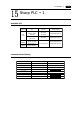
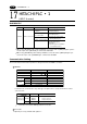
Available PLC
Host Link H-7338
*
1Specify the memory by absolute addresses. For further information, refer to the relevant PLC manual.
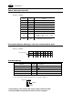
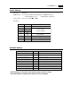
Communication Setting
The recommended communication parameter setting of both PLC and POD is as follows:
Available Memory
HIDIC-S10 2 /S10 mini
7Baud Rate
Item Setting of PLC
19200bps
Comm. Parameter of POD
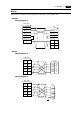
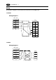
Wiring Diagram
*
1
Interface on a CPU unit
Interface on a CPU unit
RS-232C connector on a CPU unit
LQE060
RS-422 [Wiring Diagram 3]
RS-422 [Wiring Diagram 3]
RS-232C [Wiring Diagram 1]
RS-232C [Wiring Diagram 2]
RS-422 [Wiring Diagram 3]
PLC Link Unit
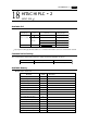
Select PLC Type
S10 2
S10 mini
ABS
HIDIC-S10/2alpha
HIDIC-S10/ABS
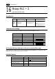
18 HITACHI PLC • 2
Memory TYPE Remarks
FW (work register) 0
X (input relay) 1 XW as word device
Y (output relay) 2 YW as word device
R (internal relay) 3 RW as word device
G (global link) 4 GW as word device
K (keep relay) 5 KW as word device
T (on-delay timer contact) 6 TW as word device
U (one shot timer contact) 7 UW as word device
C (up/down counter contact) 8 CW as word device
TS (on-delay timer set value) 9
TC (on-delay timer elapsed value) 10
US (one shot timer set value) 11
UC (one shot timer elapsed value) 12
CS (up/down counter set value) 13
CC (up/down counter elapsed value) 14
DW (data register) 15