
Home Theater Screen User Manual


2 - 94
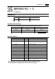
SIEMENS PLC • 2
(S5-115U/135U/155U , S7-300,400)
Available PLC
A similar program as RK512 is required.
Communication Setting
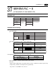
The recommended communication parameter setting of both PLC and POD is as follows:
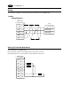
Available Memory
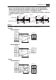
The assigned memory is indicated while
editing the screen as illustrated:
Set the memory to the extent of the memory range of each PLC model.
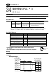
Use TYPE number to assign indirect memory for macro programs.
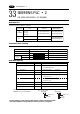
33
9600bpsBaud Rate
Parity
Transmission
Code
Data Length
Stop Bit
Item Setting of PLC
9600bps
Comm. Parameter of POD
Even (fixed)
8 (fixed)
1 (fixed)
DB003:0000
Block No.
Address No.
Colon
S7
DB003000
Block No.
Address No.
<E.g.> S5, S5 UG400
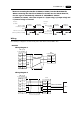
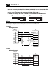
PLC Link Unit Wiring Diagram
S5-115U
S5-135U
S5-155U
RS-232C [Wiring Diagram 1]
RS-422 [Wiring Diagram 3]
RS-232C [Wiring Diagram 2]
RS-422 [Wiring Diagram 3]
CP-524(3964R/RK512)
CP-544(3964R/RK512)
Select PLC Type
S5
(S5 UG400)
S7-300
S7-400
CP-341(3964R/RK512)
CP-441(3964R/RK512)
S7
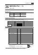
Memory TYPE Remarks
DB (data register) 0 Use memories, more than DB1 for S7,
more than DB3 for S5.
I (input relay) 1 IW as word device Read only
Q(output relay) 2 QW as word device Read only
F(internal relay) 3 FW as word device Read only
only in S5 series
M(internal relay) 3 MW as word device Read only
only in S7 series
T (timer/current value) 4 Read only
C(counter/current value) 5 Read only
AS (absolute address) 6 Can not be used in S7 series.
33 SIEMENS PLC • 2