
Home Theater Screen User Manual

3 - 14
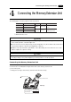
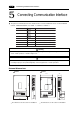
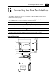
5 Connecting Communication Interface
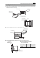
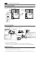
Mounting the I/F unit(UG03I-x)
•
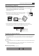
Remove the seal for preventing dust attached on the back of the POD as shown in the figure on the right.
Mount the I/F unit, then secure it using the 3 screws.
•
Route the communication cable. For details regarding how to lay and connect the communication cable,
refer to the corresponding user’s manual.
•
For the UG320/UG221, set the spacer contained in the package to the hole on the upper left side, then
mount the I/F unit.
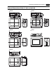
CN2
MJ1MJ2
C
N
1
100-
240VAC
L
N
NC
Mounting screws (3 positions)
*
POD
I/F unit
POD
I/F unit
MJ2 MJ1
CN2
CN1
DC24V
(
+
)
(
-
)
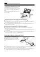
Mounting screws
(4 positions)
*
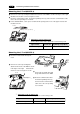
I/F unit
Notch
*
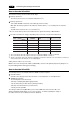
Tightening screws for fixing a unit
See the table below for how to tighten the screw for fixing a unit:
Type of screw Screw size Tightening torque (N•m)
Unit mounting screw M3 0.3 to 0.5
Mounting the I/F unit(UG02I-x)
•
Route the insulated cable through the
notch.
•
Remove the seal for preventing dust
attached on the back of the POD as shown
in the figure on the right. Mount the I/F
unit, then secure it using the 4 screws.
•
Connect the insulated cable with
the ground terminal on the POD.
•
Route the communication cable.
For details regarding how to lay
and connect the communication
cable, refer to the corresponding
user’s manual.
*
Tightening screws for fixing a unit
See the table below for how to tighten the screw for fixing a unit:
Type of screw Screw size Tightening torque (N•m)
Unit mounting screw M3 0.3 to 0.5