
Installation Instructions


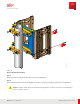
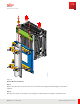
Table Of Contents
- User Guide
- Contents
- Preface
- 1 About this Guide
- 2 Overview
- 3 RU Hardware Feature
- 3.1 System Configuration
- 3.2 RU Specifications
- 3.3 Environment Specification
- 3.4 RU Downlink/Uplink Default Parameters
- 3.5 Antenna Configuration
- 3.6 Carrier Configuration
- 3.7 Block Diagram
- 3.8 External Interface
- 3.9 TX Control Function
- 3.10 Performance Requirement
- 3.11 Mechanical Design and Other Options
- 4 Ordering Information
- 5 Installation
- 6 Operations
- 7 Maintenance and Trouble Clearing
- 8 Removal
- A References
- B ZTP Overview
- C Optical Connector Cleaning
- D Glossary
- Index

Step 8
Remove weatherproofing covers from connectors.
Step 9
Locate the-48 DC power cable connection on the bot tom of the RU.
Step 10
Loosen the cable connection by rotat ing the cable-counter clockwise.
Step 11
Remove the cable from the –48V DC port on the RU and the pow er source.
Step 12
Insert a prot ective cover int o the –48V DC port.
Step 13
Verify that no pow er is present by measuring volt age on the power cable using a DM M .
✓ This task is complete.
8.1.2
Remove RF Cables
This procedure describes how to disconnect the four RF cables from the RU.
Prerequisite:
■ RU pow ered off
Step 1
Remove the weatherproofing from each connector according to local guidelines.
Step 2
Loosen each RF connection bet ween the RU and the antenna.
Step 3
Disconnect the RF cables from the RF port on the RU.
Step 4
Insert prot ective covers int o the RF port s.
Continue with the next task.
8.1.3
Remove AISG Cable
This procedure describes how to remove AISG RET cable from the RU.
Removal
Cable Removal
113
Release 1.0 · Issue 1, M arch 2021
Fujitsu and Fujitsu Customer Use Only