
Installation Instructions


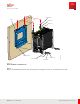


Table Of Contents
- User Guide
- Contents
- Preface
- 1 About this Guide
- 2 Overview
- 3 RU Hardware Feature
- 3.1 System Configuration
- 3.2 RU Specifications
- 3.3 Environment Specification
- 3.4 RU Downlink/Uplink Default Parameters
- 3.5 Antenna Configuration
- 3.6 Carrier Configuration
- 3.7 Block Diagram
- 3.8 External Interface
- 3.9 TX Control Function
- 3.10 Performance Requirement
- 3.11 Mechanical Design and Other Options
- 4 Ordering Information
- 5 Installation
- 6 Operations
- 7 Maintenance and Trouble Clearing
- 8 Removal
- A References
- B ZTP Overview
- C Optical Connector Cleaning
- D Glossary
- Index

8.5
Remove L-Brackets and Eye Bolts
This procedure describes how to remove the L-bracket s and eye bolt s from the RU.
Prerequisites:
Recommended Tools:
■ 1/ 2, 7/ 16, and 11/ 16 socket s
■ 5/ 8 wrench
■ Philips screw driver
■ Power tools (optional)
Step 1
Unscrew the two M 8 eye bolts from the tw o holes on top of the RU and collect the washers.
Step 2
Unscrew the eight M 8 screws on the L-bracket s on each side of the RU.
Step 3
Remove the L-bracket s from each side of the RU.
Removal
Remove L-Brackets and Eye Bolts
126
Release 1.0 · Issue 1, M arch 2021
Fujitsu and Fujitsu Customer Use Only