
Installation Instructions

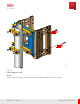
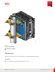
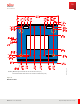
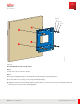
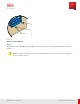
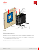
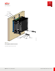
Table Of Contents
- User Guide
- Contents
- Preface
- 1 About this Guide
- 2 Overview
- 3 RU Hardware Feature
- 3.1 System Configuration
- 3.2 RU Specifications
- 3.3 Environment Specifications
- 3.4 RU Downlink/Uplink Default Parameters
- 3.5 Antenna Configuration
- 3.6 Carrier Configuration
- 3.7 Block Diagram
- 3.8 External Interface
- 3.9 TX Control Function
- 3.10 Performance Requirement
- 3.11 Mechanical Design and Other Options
- 4 Ordering Information
- 5 Installation
- 6 Operations
- 7 Maintenance and Trouble Clearing
- 8 Removal
- A References
- B ZTP Overview
- C Optical Connector Cleaning
- D Glossary
- Index

Insulating Bushing
FNC001626_Rev_01
Figure 28
Adhesive Insulating Bushing
Step 4
Align the holes on the Wall M ount Plate Adapt er wit h the holes on the top of the Wall M ount Plate and hook it
in place.
Caution: The RU is heavy. Fujit su recommends installing the RU on a two-person team to avoid damage to
the unit or injury to the user.
Installation
RU Installation
96
Release 1.0 · Issue 1, M arch 2021
Fujitsu and Fujitsu Customer Use Only