User Guide control BX600 Digital KVM Switch Keyboard/Video/Mouse Switch 590-673-501A English 2
USA Notification Warning: Changes or modifications to this unit not expressly approved by the party responsible for compliance could void the user’s authority to operate the equipment. Note: This equipment has been tested and found to comply with the limits for a Class A digital device, pursuant to Part 15 of the FCC Rules. These limits are designed to provide reasonable protection against harmful interference when the equipment is operated in a commercial environment.
BX600 Digital KVM Switch Edition September 2006
Comments... Suggestions... Corrections The User Documentation Department would like to know your opinion of this manual. Your feedback helps us optimize our documentation to suit your individual needs. Contact information is included in the back of the manual.
Contents 1 1.1 1.1.1 1.1.2 1.1.3 1.1.4 1.1.5 1.1.6 1.1.7 1.2 2 2.1 2.2 2.2.1 3 3.1 3.2 3.2.0.1 3.2.0.2 3.3 3.4 3.4.1 3.4.2 3.4.3 3.4.4 3.5 3.6 4 4.1 4.2 4.2.1 4.2.2 4.2.3 4.2.4 4.2.5 4.2.6 4.2.7 4.2.8 4.2.9 590-673-501A Product Overview .................................................................................... 1 Features and Benefits ............................................................................... 1 OSCAR Graphical User Interface.....................................................
Contents 4.2.10 4.2.11 4.2.12 4.2.13 4.3 4.3.1 4.3.1.1 4.3.1.2 4.3.1.3 5 5.1 5.2 5.3 5.4 5.5 5.6 6 6.1 6.2 6.3 6.4 6.4.1 590-673-501A Minimizing Remote Video Session Discoloration .................................... 29 Improving Screen Background Color Display.......................................... 30 Improving Mouse Performance ............................................................... 30 Create Snapshot Images.........................................................................
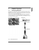
1 Product Overview 1.1 Features and Benefits The Fujitsu Siemens BX600 Digital KVM Switch is integrated in your Fujitsu Siemens BX600 blade chassis. It allows you to manage many server modules through a single keyboard, monitor, and mouse. In addition, through virtual media, you can control your remote servers as if you were physically present. You can also connect cables from the BX600 Digital KVM Switch to a KVM appliance such as the Fujitsu Siemens s3-1621 Console Switch.
OSCAR Graphical User Interface 1.1.1 Product Overview OSCAR Graphical User Interface Select the server you would like and then manage it using the On Screen Configuration and Activity Reporting (OSCAR) interface. OSCAR’s intuitive menus make managing your BX600 Digital KVM Switch system easy. 1.1.
Product Overview Title Notational Conventions This indicates information, which if not heeded, may jeopardize your health, the functioning of your system or the security of your data. This indicates a step that you have to perform. - and • These characters symbolize itemized lists. Bold monospace font This indicates user inputs in examples.
Notational Conventions 4 Product Overview 590-673-501A
2 Installation You can deploy the BX600 Digital KVM Switch Module into most existing KVM infrastructures. In addition, you can set up the BX600 Digital KVM Switch in tiers from Fujitsu Siemens branded KVM appliances such as the Fujitsu Siemens s3-1621 Console Switch and analog s2-0801 and s2-1602 switches. It can also be tiered from other industry products that support the OSCAR interface. 2.
Setting Up a BX600 Digital KVM Switch in Tiers Installation To display the BX600 Digital KVM Switch Main dialog box by slot order: Press Print Screen to launch OSCAR, the BX600 Digital KVM Switch interface. Click Setup and then click Menu. The Menu dialog box appears. Figure 3: Menu Dialog Box Select Slot to display servers by slot number. Type a screen delay time of 1 second. Click OK. 2.
Installation Setting Up a BX600 Digital KVM Switch in Tiers NOTE: If the KVM appliance is powered on before the BX600 blade chassis, it may result in only 1 blade sever displaying in the KVM appliance interface instead of 10. NOTE: In addition to the steps outlined above, some KVM appliances may require you to perform additional steps to ensure that the BX600 Digital KVM Switch blade servers appear in the KVM appliance interface. Please read your KVM appliance documentation for additional information.
Tiering a BX600 Digital KVM Switch from a KVMs3-1621 or To configure the KVM appliance: Press Print Screen to open the OSCAR Main dialog box. Click Setup then click Devices and then click Device Modify. Figure 5: Device Modify Dialog Box Select the 10-port option to match the number of slots in the BX600 blade chassis. If the 10-port option is not available, select the 16-port option. Click OK to exit OSCAR. Press Print Screen to verify that the settings have taken effect.
Installation Tiering a BX600 Digital KVM Switch from a KVMs3-1621 Connect the other end of the CAT5 cable to a KVM Intelligent Adaptor (KVM-IA). Connect the local KVM cable to the local KVM port of the BX600 Digital KVM Switch and then to the KVM-IA. Once the BX600 Digital KVM Switch is connected, the server blades appear in OSCAR.
Tiering a BX600 Digital KVM Switch from a KVMs3-1621 or 10 590-673-501A
3 Analog Operation 3.1 Controlling Your System The BX600 Digital KVM Switch uses the intuitive menus of the OSCAR interface to allow you to select server modules and configure your system. 3.2 Viewing and Selecting Slots and Server Modules Use the Main dialog box to view, configure, and control server modules connected to the BX600 Digital KVM Switch. You can view your server modules by name or by slot, but by default, you will see a Name list when you first launch OSCAR.
Viewing and Selecting Slots and Server Modules Analog Operation Symbol Description Server Module is online PS/2 subsystem firmware is upgrading Server Module is offline or is not operating properly User connection Table 1: OSCAR Status Symbols 3.2.0.1 Selecting Server Modules When you select a Server Module, the BX600 Digital KVM Switch reconfigures the keyboard and mouse to the proper settings for that Server Module. To select server modules: Double-click the Server Module name or slot number.
Analog Operation OSCAR Navigation Basics Click Setup and then click Menu. The Menu dialog box appears. Select Name or Slot for the Display/Sort Key. For Delay Time, type the number of seconds of delay desired before the Main dialog box is displayed after Print Screen is pressed. Click OK. To soft switch to a Server Module: To select a Server Module, press Print Screen.
Configuring OSCAR Analog Operation Keystroke Result Single-click Enter In a text box, it selects the text for editing and enables the leftarrow and right-arrow keys to move the cursor. Press Enter again to quit the edit mode. Print Screen, Backspace Toggles back to previous selection if no other keystrokes have been typed. Print Screen, Alt+Ø Immediately disconnects the analog user from a Server Module; no Server Module is selected. Status flag displays Free.
Analog Operation Assigning Server Module Names Figure 9: Setup Dialog Box 3.4.1 Assigning Server Module Names Use the Names dialog box to identify server modules by name rather than by slot number. The Names list is always sorted by slot order. To access the Names dialog box: Press Print Screen. The Main dialog box will appear. Click Setup and then click Names. The Names dialog box appears.
Changing the Display Behavior Analog Operation Figure 11: Name Modify Dialog Box Type a name in the New Name field. Names of server modules may be up to 15 characters long. Allowable characters include: A-Z, a-z, Ø-9, space and hyphen. Click OK to transfer the new name to the Names dialog box. Your selection is not saved until you click OK in the Names dialog box. Repeat steps 1-3 for each Server Module in the system. Click OK in the Names dialog box to save your changes.
Analog Operation Controlling the Status Flag -orSelect Slot to display server modules numerically by slot number. Click OK. To set a screen delay time for OSCAR: Type in the number of seconds (Ø-9) you want to delay display of OSCAR after you press Print Screen. Entering Ø will instantly launch OSCAR with no delay. Click OK. Setting a time to delay display of OSCAR allows you to complete a soft switch without OSCAR displaying. To perform a soft switch, see “Soft Switching” on page 12. 3.4.
Setting Console Security Analog Operation To determine how the status flag is displayed: Select Displayed to show the flag all the time or select Displayed and Timed to display the flag for only five seconds after switching. NOTE: If only Timed is selected the flag will not be displayed at all. Select a flag color in Display Color. The flag numbers represent Flag 1, black; Flag 2, red, Flag 3, blue; and 4, purple.
Analog Operation Setting Console Security Figure 15: Security Dialog Box To set or change the password: CAUTION: There is no master password. The BX600 appliance must be sent to Fujitsu Siemens in the case of a lost password. Single-click and press Enter or double-click in the New text box. Type the new password in the New text box and press Enter. Passwords require 5 to 12 characters and must include at least one letter and one number. Passwords are also case sensitive.
Setting Console Security Analog Operation To automatically log out of a Server Module when inactive: In the Main dialog box, click Setup and then click Security. If you have password protection, the Password dialog box appears. Type your password, and then click OK. The Security dialog box appears. In the Inactivity Time field, enter the length of time you want to stay connected to a Server Module before it automatically disengages you. Click OK.
Analog Operation Displaying Version Information To turn off the screen saver: In the Security dialog box, clear Enable Screen Saver. Click OK. To immediately turn on the screen saver: Press Print Screen, then press Pause. NOTE: Enable Screen Saver must be selected in the Security dialog box. 3.5 Displaying Version Information Use the Version dialog box to display the BX600 Digital KVM Switch firmware, hardware and FPGA versions, and to identify the language and keyboard configuration.
Scanning Your System Analog Operation Figure 17: Scan Dialog Box The dialog box contains a listing of all the server modules attached to your unit. Click to enable the check box next to the server modules you wish to scan. -orDouble-click on a Server Module's name or slot. -orPress Alt+ the number of the Server Module you wish to scan. You can select up to 10 server modules.
Analog Operation Scanning Your System Figure 18: Command Dialog Box 3 Select Scan Enable in the Command dialog box. To cancel scan mode: Select a Server Module if OSCAR is open. -orMove the mouse or press any key on the keyboard if OSCAR is not open. Scanning will stop at the currently selected Server Module. -orPress Print Screen. The Main dialog box will appear. Click Commands. The Command dialog box appears. Clear Scan Enable.
Scanning Your System 24 Analog Operation 590-673-501A
4 Digital Operation The BX600 Digital KVM Switch allows you to manage both blade servers and virtual media from a remote location. Using the Video Viewer, you can view and manage any of ten blade servers remotely in exactly the same way that you would if you were sitting in front of them. Using the Virtual Media dialog box, you can manage virtual media sessions allowing you to remotely perform server backups, recovery operations, and operating system installation to name a few examples.
Using the Video Viewer Digital Operation Click on the plus sign (+) next to the DKVM folder in the left column to display the folder’s contents. On the left side, select Console Redirection. On the right side, select the Server Blade from the drop-down list. Click on Launch. 4.2 Using the Video Viewer Once you have selected Console in the MMB menu, you may select the server you would like to interact with. To access a server: Click the Servers button in the list of servers.
Digital Operation 4.2.2 Viewer Window Features Viewer Window Features Figure 20: Video Viewer Application 4.2.3 Expanding and Refreshing Your Viewer You can adjust your view of the remote system’s monitor using the buttons at the bottom of the Viewer window. The buttons allow you to set video adjustments, refresh the screen, capture screen images, get help and close the Video Viewer application.
Adjusting the Viewer Window Digital Operation To close the Video Viewer application: Click Close on the viewer toolbar. 4.2.4 You can adjust both the size and quality of the server’s Viewer. You can also expand your Viewer to fit the entire screen or refresh the view at any time. 4.2.5 Adjusting the Viewer Window Adjusting Keyboard Macros Allows you to select and type a number of keystroke combinations that cannot be typed using your local keyboard without affecting your local system.
Digital Operation 4.2.
Improving Screen Background Color Display Digital Operation condition is minimized by using a black background. If a color background is used, a small number of pixels on the screen will be discolored or white. To minimize remote video pixel discoloration: In the Viewer, click Calibrate. The Auto Video Adjust dialog box appears. Click the Manual Video Adjust button. Choose contrast or brightness. Adjust the contrast and brightness until the image quality improves.
Digital Operation Create Snapshot Images Intellipoint Drivers (Only for Windows based Operating Systems): Select Start then select Settings and then select Control Panel. Double-click the Mouse icon. Cycle through the tabs until the pointer speed slider is displayed. Adjust the mouse speed to the exact midpoint of the slider bar. Click Advanced. Click the Acceleration check box to turn off acceleration. Click OK.
Virtual Media Dialog Box Digital Operation Figure 22: Virtual Media page of the MMB menu To access a server: Click the Select Device drop-down list in the list of servers. Select the server on which you want to attach your virtual media. The launch button will become active. Click the Launch button. The Virtual Media dialog box will appear. It will be associated with the server you chose from the drop-down list. 4.3.1.
Digital Operation Virtual Media Dialog Box 4.3.1.2 Mapping a CD/DVD Device The CD/DVD Devices or Filesystem panel allows you to select a CD/DVD device from the attached CD/DVD drives. You can also select the ISO Image option to select a single CD/DVD image file. If you do not want to select either of these options you can select the No CD/DVD option. NOTE: Only one CD/DVD Devices or Filesystem option can be selected at any one time.
Virtual Media Dialog Box 34 Digital Operation 590-673-501A
5 BX600 Graphical User Interface The Fujitsu Siemens BX600 Digital KVM Switch allows you to access the blades in a BX600 Blade Server using a Graphical User Interface (GUI). To access the Fujitsu Siemens Management Blade (MMB) GUI: Point your browser to the IP address of the MMB to access the BX600 Digital KVM Switch.
Network Configuration • BX600 Graphical User Interface DKVM blade Hardware Version 5.3 Network Configuration In order for you to have GUI access to the BX600 Digital KVM switch, you must assign a valid IP address to it. NOTE: If your local area network is configured for DHCP, you should check the DHCP check box and you can skip the first three steps of the following task.
BX600 Graphical User Interface Console Redirection Figure 24: DKVM Network Configuration Page of the MMB Menu 5.4 Console Redirection The Console Redirection page is the page that you use to launch the Video Viewer application. To redirect the console to a Video Viewer of your selected blade server: Select Console Redirection from inside the DKVM Blade folder in the left column. Select a blade server from the drop-down list in the screen that appears. Click on Launch.
Virtual Media 5.5 BX600 Graphical User Interface Virtual Media The BX600 Digital KVM switch allows you to use media on your local workstation as if it were installed on the remote blade server. This feature is known as virtual media. To launch the Virtual Media Dialog Box: Select Virtual Media from inside the DKVM Blade folder in the left column. Select a blade server from the drop-down list in the screen that appears. Click on Launch.
6 Appendices 6.1 Technical Publications Server Module Slots Number 10 Plug and Play DDC2B Video Resolution Analog Port Maximum 1600x1200@75Hz. Ethernet Port Number 1 Connectors RJ45 Analog Port Number 1 Type PS/2 and VGA Connectors PS/2 MiniDIN, 15 Pin D Table 1: Technical Specifications 6.
OSCAR Refresh Rates • Appendices Java JRE version 1.4.2 or later 6.3 OSCAR Refresh Rates On-Screen Configuration and Activity Reporting interface (OSCAR®) synchronizes to the following refresh rates. Resolution Refresh Rate Horizontal Frequency 640 x 480 60 Hz 31.5 Khz 640 x 480 72 Hz 37.9 Khz 640 x 480 75 Hz 37.5 Khz 640 x 480 85 Hz 43.3 Khz 800 x 600 60 Hz 37.9 Khz 800 x 600 72 Hz 48.1 Khz 800 x 600 75 Hz 46.9 Khz 800 x 600 85 Hz 53.7 Khz 1024 x 768 60 Hz 48.
Appendices Technical Support Resolution Refresh Rate Horizontal Frequency 1600 x 1200 85 Hz 106.3 Khz Table 2: Refresh Rates (Continued) 6.4 Technical Support Our Technical Support staff is ready to assist you with any installation or operating issues you encounter with your Fujitsu Siemens product.
Before you call 42 Appendices 590-673-501A