PRIMERGY TX120 Server Options Guide Edition August 2007
Comments… Suggestions… Corrections… The User Documentation Department would like to know your opinion of this manual. Your feedback helps us optimize our documentation to suit your individual needs. Feel free to send us your comments by e-mail to manuals@fujitsu-siemens.com.
Contents 1 Introduction . . . . . . . . . . . . . . . . . . . . . . . . . . . . 5 1.1 Concept and target groups . . . . . . . . . . . . . . . . . . . 5 1.2 Documentation overview 1.3 Expansions and conversions . . . . . . . . . . . . . . . . . . 8 1.4 Notational conventions 2 Procedure . . . . . . . . . . . . . . . . . . . . . . . . . . . . 11 3 Safety . . . . . . . . . . . . . . . . . . . . . . . . . . . . . . 13 4 Preparation . . . . . . . . . . . . . . . . . . . . . . . . . . . 19 4.
Contents 7 Expansion cards in the PCI slots . . . . . . . . . . . . . . . . 37 7.1 PCI slot overview . . . . . . . . . . . . . . . . . . . . . . . . 37 7.2 Installing an expansion card . . . . . . . . . . . . . . . . . . 38 8 Completion . . . . . . . . . . . . . . . . . . . . . . . . . . . . 41 8.1 Installing the drive cage . . . . . . . . . . . . . . . . . . . . . 41 8.2 Installing the crosspiece . . . . . . . . . . . . . . . . . . . . 43 8.3 Assembling the server . . . . . . . . . . . . . . .
1 Introduction The PRIMERGY TX120 server is an Intel-based server for small and mediumsized networks and can be used in the horizontal position or as a desktop model. The PRIMERGY TX120 server features exceptionally low energy consumption, very quiet running and a compact size. As a result, it is also the ideal solution for home and small offices. Thanks to its highly developed hardware and software components, the PRIMERGY TX120 server offers a high level of data security and availability.
Documentation overview 1.
Introduction Documentation overview I PRIMERGY manuals are available in PDF format on the ServerBooks DVD. The ServerBooks DVD is part of the ServerStart Suite supplied with every server. The PDF files of the manuals can also be downloaded free of charge from the Internet. The overview page showing the online documentation available on the Internet can be found using the URL: http://manuals.fujitsu-siemens.com.
Expansions and conversions 1.3 Introduction Expansions and conversions Main memory expansion The system board supports up to 8 Gbyte of main memory. 4 slots (2 memory banks with 2 slots each) are provided for the main memory. Each memory bank can be equippeded with 512 Mbyte, 1 Gbyte or 2 Gbyte unbuffered DDR2 memory modules. If the memory modules are installed in pairs, they must be identical (2-way interleaved mode). Additional accessible drive A 3.
Introduction 1.4 Notational conventions Notational conventions The following notational conventions are used in this manual: Text in italics indicates commands, menu items or software programs. “Quotation marks” indicate names of chapters and terms that are being emphasized. Ê describes activities that must be performed in the order shown. V CAUTION! I TX120 pay particular attention to texts marked with this symbol.
2 Procedure V CAUTION! ● The actions described in this manual should only be performed by technical specialists. ● Equipment repairs should only be performed by service personnel. ● Any unauthorized opening and improper repairs could expose the user to risks (electric shock, energy hazards, fire hazards) and could also damage the equipment. ● Any unauthorized opening of the device will result in the invalidation of the warranty and exclusion from all liability.
3 Safety I The following safety instructions are also provided in the manual “Safety notes and other important information”. This device complies with the relevant safety regulations for data processing equipment. If you have any questions about where you can set up the device, contact your sales outlet or our customer service team. V CAUTION! TX120 ● The actions described in this manual should only be performed by technical specialists.
Safety Before starting up V CAUTION! ● During installation and before operating the device, observe the instructions on environmental conditions for your device. ● If the device is brought in from a cold environment, condensation may form both inside and on the outside of the device. Wait until the device has acclimatized to room temperature and is absolutely dry before starting it up. Material damage may be caused to the device if this requirement is not observed.
Safety V CAUTION! TX120 ● Ensure that the power sockets on the device and the grounded shockproof sockets are freely accessible. ● The On/Off button or the main power switch (if present) does not isolate the device from the mains power supply. To disconnect it completely from the mains power supply, unplug all network power plugs from the grounded shockproof sockets. ● Always connect the server and the attached peripherals to the same power circuit. Otherwise you run the risk of losing data if, for.
Safety V CAUTION! ● Proper operation of the system (in accordance with IEC 60950-1/EN 60950-1) is only ensured if the casing is completely assembled and the rear covers for the installation slots have been fitted (electric shock, cooling, fire protection, interference suppression). ● Only install system expansions that satisfy the requirements and rules governing safety and electromagnetic compatibility and those relating to telecommunication terminals.
Safety Working with CDs/DVDs and CD/DVD drives When working with devices with CD/DVD drives, these instructions must be followed. V CAUTION! ● Only use CDs/DVDs that are in perfect condition in your server's CD/DVD drive, in order to prevent data loss, equipment damage and injury. ● Check each CD/DVD for damage, cracks, breakages etc. before inserting it in the drive. Note that any additional labels applied may change the mechanical properties of a CD/DVD and cause imbalance.
Safety Modules with electrostatic-sensitive components Systems and components that might be damaged by electrostatic discharge (ESD) are marked with the following label: Figure 1: ESD label When you handle components fitted with ESDs, you must observe the following points under all circumstances: ● Remove the power plug before installing or removing components containing ESDs. ● You must always discharge yourself of static charges (e.g. by touching a grounded object) before working.
4 Preparation V CAUTION! Please note the safety instructions in chapter “Safety” on page 13. 4.1 Opening the server Ê Exit all applications and shut down the server properly. Ê Press the On/Off button if the server has not been switched off by the operating system. Ê Unplug all power plugs. Ê Disconnect all cables on the rear of the server.
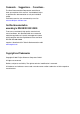
Removing the crosspiece 4.2 Preparation Removing the crosspiece 2 1 3 Figure 3: Removing the crosspiece Ê Pull the crosspiece out a little to the side (1). Ê Unhook the crosspiece on the left (2). Ê Carefully remove the crosspiece (3).
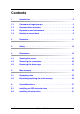
Preparation 4.3 Removing the drive cage Removing the drive cage 1 2 4 5 3 Figure 4: Disconnecting the cables Ê Disconnect the following cables from the SAS backplane (1-3) and from the CD/DVD drive (4-5): 1. Power cable 2. SAS data cable 3. SAS-LED cable 4. Power cable 5.
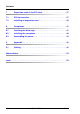
Removing the drive cage Preparation 1 2 Figure 5: Removing the drive cage Ê Disengage the lock of the drive cage (1). Ê Pull out the drive cage in the direction of the arrow (2).
5 Main memory V CAUTION! Please note the safety instructions in chapter “Safety” on page 13. The system board supports up to 8 Gbyte of main memory. 4 slots (2 memory banks with 2 slots each) are provided for the main memory. Each memory bank can be equippeded with 512 Mbyte, 1 Gbyte or 2 Gbyte unbuffered DDR2 memory modules. 5.
Equipping rules Main memory – If the memory modules are installed in pairs, they must be identical (2-way interleaved mode). – Memory module capacity may be different for the various pairs: e.g. pair 2A/2B may be equipped with two 512 Mbyte memory modules, and pair 1A/1B may be equipped with two 1 Gbyte memory modules.
Main memory 5.2 Expanding/replacing the main memory Expanding/replacing the main memory Ê Open the server (see section “Opening the server” on page 19). Ê Remove the crosspiece (see section “Removing the crosspiece” on page 20). Removing a memory module 2 1 1 Figure 7: Removing a memory module Ê Fold the assembly brackets outwards on both sides of the corresponding slot (1). Ê If the slot was equipped: pull the memory module out of the slot (2).
Expanding/replacing the main memory Main memory Installing a memory module Figure 8: Installing a memory module Ê Fold the assembly brackets outwards on both sides of the corresponding slot. Ê Insert the memory module into the slot with the connecting contacts and the notch first until the side brackets engage on the memory module. Ê Install the crosspiece (see section “Installing the crosspiece” on page 43). Ê Close the server (see section “Assembling the server” on page 44).
6 Accessible drives V CAUTION! Follow the safety instructions in chapter “Safety” on page 13. A 3.5-inch bay for an HDD extension box (with a maximum of two HDD modules) or a backup drive is available. 6.1 Installing an HDD extension box Ê Open the server (see section “Opening the server” on page 19). Ê Remove the crosspiece (see section “Removing the crosspiece” on page 20). Ê Remove the drive cage (see section “Removing the drive cage” on page 21).
Installing an HDD extension box Accessible drives Figure 10: Fixing the rails on the HDD extension box Ê Fix the rails to the HDD extension box by inserting the pins on the rail in the corresponding holes in the HDD extension box.
Accessible drives Installing an HDD extension box Figure 11: Installing an HDD extension box Ê Slide the HDD extension box into the slot. Ê Connect the SAS data cable to the HDD extension box (see cabling diagrams in the appendix). Ê Connect the power cable to the HDD extension box (see cabling diagrams in the appendix). Ê Connect the SAS LED cable to the HDD extension box (see cabling diagrams in the appendix). Ê Install the drive cage (see section “Installing the drive cage” on page 41).
Installing an HDD extension box Accessible drives Figure 12: Removing the dummy cover from the top cover Ê Press the dummy cover outwards from the top cover in the direction of the arrow. V CAUTION! Keep the dummy cover in a safe place. If the HDD extension box is removed again and not replaced with a new one, then the dummy cover must be reinstalled due to cooling, the applicable EMC regulations (regulations on electromagnetic compatibility) and fire protection.
Accessible drives 6.2 Installing a backup drive Installing a backup drive Ê Open the server (see section “Opening the server” on page 19). Ê Remove the crosspiece (see section “Removing the crosspiece” on page 20). Ê Remove the drive cage (see section “Removing the drive cage” on page 21). Figure 13: Removing the protection shield from the 3.5-inch bay Ê Grasp the protection shield through the holes and pull it out in the direction of the arrow. V CAUTION! Store the protection shield in a safe place.
Installing a backup drive Accessible drives Figure 14: Fixing the rails on the backup drive Ê Fix the rails on the backup drive by inserting the pins on the rails in the corresponding holes in the backup drive. Figure 15: Installing a backup drive Ê Insert the backup drive into the location.
Accessible drives Installing a backup drive Figure 16: Unfastening the cable clamp Ê Unfasten the cable clamp.
Installing a backup drive Accessible drives 1 2 Figure 17: Connecting the USB and power cables to the backup drive Ê Plug the USB cable (1) and the power cable (2) into the backup drive (see cabling diagrams in the appendix). Ê Plug the other end of the USB cable into the system board (see cabling diagrams in the appendix). Ê Install the drive cage (see section “Installing the drive cage” on page 41). Ê Install the crosspiece (see section “Installing the crosspiece” on page 43).
Accessible drives Installing a backup drive Figure 18: Removing the dummy cover from the top cover Ê Press the dummy cover outwards from the top cover in the direction of the arrow. V CAUTION! Keep the dummy cover in a safe place. If the backup drive is removed again and not replaced with a new one, then the dummy cover must be reinstalled due to cooling, the applicable EMC regulations (regulations on electromagnetic compatibility) and fire protection.
7 Expansion cards in the PCI slots V CAUTION! Follow the safety instructions in chapter “Safety” on page 13. 7.
Installing an expansion card 7.2 Expansion cards in the PCI slots Installing an expansion card Ê Open the server (see section “Opening the server” on page 19). Ê Please read the documentation supplied with the expansion card. 3 1 2 1 Figure 20: Opening the lock and removing the slot cover Ê Press the lock together (1) and open it up (2). Ê Pull out the slot cover (3). V CAUTION! Keep the slot cover in a safe place.
Expansion cards in the PCI slots Installing an expansion card Figure 21: Installing an expansion card Ê Push the expansion card as far as it will go into the slot on the system board. Ê Press the expansion card into the slot until you feel it click into place.
Installing an expansion card Expansion cards in the PCI slots Figure 22: Closing the lock and fastening the slot cover Ê Close the lock again until it engages. Ê If necessary, connect the cable to the expansion card and the other components. Ê Close the server (see section “Assembling the server” on page 44). Ê If necessary, place the server in the vertical position as described in the operating manual Ê Connect the system to the line voltage and switch it on.
8 Completion V CAUTION! Follow the safety instructions in chapter “Safety” on page 13. 8.1 Installing the drive cage a 1 2 a Figure 23: Installing the drive cage Ê Place the drive cage on the 3.5-inch bay (1), so that the four tabs in the housing (a) are positioned in the corresponding openings. Ê Slide the drive cage in the direction of the arrow (2) until it clicks into place.
Installing the drive cage Completion 1 2 4 5 3 Figure 24: Connecting the cables Ê Plug the power cable (1), the SAS data cable (2) and the SAS LED cable (3) into the SAS backplane (see cabling diagrams in the appendix). Ê Plug the power cable (4) and the IDE cable (5) into the CD/DVD drive (see cabling diagrams in the appendix).
Completion 8.2 Installing the crosspiece Installing the crosspiece 1 2 3 Figure 25: Installing the crosspiece Ê Hook the crosspiece on the left in place (1). Ê Press on the right side of the crosspiece (2) until you feel it click into place.
Assembling the server 8.3 Completion Assembling the server Figure 26: Assembling the server Ê Place the top cover flat and straight on the server and push it as far as it will go in the direction of the arrow. Make sure that the locks on both sides of the server engage.
9 Appendix 9.
Cabling Appendix Legend: Data ATX PSU /4 PIN CPU SYS USB I2C SATA Power Adapter SAS ATA 100 ATX PSU / 24PIN IDE FAN2 SYS FRONTPANEL ATX-Power IDE PRIMARY SAS 1-4 UP LOWER INTRUSION BPL LED BPL LED SYS FAN1 USB DAT SATA <- P1 <- P7 PSU E516-V50 P5 -> P3 -> P2 -> (top) optical optical Drive Drive UPPER SAS BPL 1x2.
Appendix Cabling Legend: Data ATX PSU /4 PIN CPU SYS USB I2C SATA Power Adapter SAS ATA 100 ATX PSU / 24PIN IDE FAN2 SYS FRONTPANEL ATX-Power IDE PRIMARY SAS 1-4 UP LOWER INTRUSION BPL LED BPL LED SYS FAN1 USB DAT SATA <- P1 <- P7 PSU E516-V50 P5 -> P3 -> P2 -> CN1 (top) UPPER SAS BPL LOWER SAS BPL optical optical Drive Drive Port1 Port2 X6 BPL LED Port3 BPL LED S26361-K1109-V***-*-12 Port4 PRIMERGY TX120 / D2550 Overview Cabling Power cable E416-V50 2x2.
Cabling Appendix Legend: Data ATX PSU /4 PIN CPU SYS USB I2C SATA Power Adapter SAS ATA 100 ATX PSU / 24PIN IDE FAN2 SYS FRONTPANEL ATX-Power IDE PRIMARY SAS 1-4 UP LOWER INTRUSION BPL LED BPL LED USB DAT SYS FAN1 SATA <- P1 <- P7 PSU E516-V50 P5 -> CN1 (top) UPPER SAS BPL optical optical Drive Drive Port1 S26361-K1109-V***-*-12 Port2 BPL LED USB TAPE 1x2.
Appendix Cabling Legend: ATX PSU /4 PIN Data CPU SYS USB I2C SATA CPU FAN Power Adapter SAS ATA 100 ATX PSU / 24PIN IDE SYS FAN2 FRONTPANEL ATX-Power IDE PRIMARY SAS 1-4 UP LOWER BPL LED BPL LED USB DAT SATA SYS FAN1 A3C40083123 SYS FAN2 SYS FAN1 Frontpanel PRIMERGY TX120 / D2550 Overview Cabling Data cable System with AdOn SAS controller FP, Int & FAN‘s S26361-K1109-V***-*-12 Figure 30: Cabling: fan, control panel (front panel) TX120 Options Guide 49
Cabling Appendix Legend: Data ATX PSU /4 PIN CPU SYS USB IC 2 SATA Power Adapter SAS ATA 100 ATX PSU / 24PIN IDE FAN2 SYS ATX-Power FRONTPANEL UP BPL LED IDE PRIMARY SAS 1-4 LOWER BPL LED SYS FAN1 USB DAT INTRUSION SATA 3 1 2 optical Drive optical Drive (top) UPPER SAS BPL S26361-K1109-V***-*-12 CN1 Port1 Port2 BPL LED Overview Cabling Data cable System with AdOn SAS controller 2.5“ back plane & opt.
Appendix Cabling Legend: Data ATX PSU /4 PIN CPU SYS USB IC 2 SATA Power Adapter SAS ATA 100 ATX PSU / 24PIN IDE FAN2 SYS ATX-Power IDE PRIMARY LOWER BPL LED FRONTPANEL UP BPL LED SAS 1-4 INTRUSION SYS FAN1 USB DAT SATA A3C40083117 1 2 CN1 Port1 Port2 CN1 BPL Port1 UPPER SAS BPL LOWER SAS BPL optical Drive optical Drive (top) LED LED S26361-K1109-V***-*-12 Port2 BPL Overview Cabling Data cable System with AdOn SAS controller 2x 2.5“ back plane & opt.
Cabling Appendix Legend: Data ATX PSU /4 PIN CPU SYS USB I2C SATA Power Adapter SAS ATA 100 ATX PSU / 24PIN IDE FAN2 SYS FRONTPANEL UP BPL LED ATX-Power IDE PRIMARY SAS 1-4 LOWER BPL LED SYS FAN1 USB DAT INTRUSION SATA A3C40083117 TAPE optical Drive (top) (Option) 3 2 1 optical Drive optical Drive (top) UPPER SAS BPL S26361-K1109-V***-*-12 CN1 Port1 BPL LED Port2 Overview Cabling Data cable System with AdOn SAS controller 2.5“ back plane, opt.
Abbreviations AC Alternating Current ANSI American National Standard Institute ASR&R Automatic Server Reconfiguration and Restart BIOS Basic Input-Output System BMC Baseboard Management Controller CC Cache Coherency CD Compact Disk CD-ROM Compact Disk-Read Only Memory CHS Cylinder Head Sector CMOS Complementary Metal Oxide Semiconductor COM Communication CPU Central Processing Unit DC Direct Current TX120 Options Guide 53
Abbreviations DIMM Dual Inline Memory Module DIP Dual Inline Package DMA Direct Memory Access DMI Desktop Management Interface ECC Error Checking and Correcting ECP Extended Capabilities Port EEPROM Electrically Erasable Programmable Read-Only Memory EGB Elektrostatisch Gefährdete Bauteile EMP Emergency Management Port EPP Enhanced Parallel Port EMV Elektromagnetische Verträglichkeit FPC Front Panel Controller FRU Field Replaceable Unit FSB Front Side Bus 54 Options Guide TX120
Abbreviations GAM Global Array Manager GUI Graphical User Interface HDD Hard Disk Drive HSC Hot-Swap Controller I²C Inter-Integrated Circuit I/O Input/Output ICM Intelligent Chassis Management ID Identification IDE Integrated Drive Electronics IOOP Intelligent Organization of PCI iRMC integrated Remote Management Controller IRQ Interrupt Request Line LAN Local Area Network LBA Logical Block Address TX120 Options Guide 55
Abbreviations LCD Liquid Crystal Display LUN Logical Unit Number LVD Low-Voltage Differential SCSI LWL LichtWellenLeiter MMF Multi Mode Faser MRL Manually Retention Latch NMI Non Maskable Interrupt NVRAM Non Volatile Random Access Memory OS Operating System PCI Peripheral Component Interconnect PDA Prefailure Detection and Analyzing POST Power ON Self Test RAID Redundant Arrays of Independent Disks RAM Random Access Memory 56 Options Guide TX120
Abbreviations ROM Read-Only Memory RSB RemoteView Service Board RTC Real Time Clock RTDS Remote Test- und Diagnose-System SAF-TE SCSI Accessed Fault-Tolerance Enclosures SAS Serial Attached SCSI SATA Serial ATA SBE Single Bit Error SCA Single Connector Attachment SCSI Small Computer System Interface SDR Sensor Data Record SDRAM Synchronous Dynamic Random Access Memory SEL System Event Log SMI System Management Interrupt TX120 Options Guide 57
Abbreviations SSU System Setup Utility SVGA Super Video Graphics Adapter USB Universal Serial Bus VGA Video Graphics Adapter ZCR Zero Channel RAID 58 Options Guide TX120
Index installing an HDD extension box 3.