
- Siemens Computers Network Cables User Manual

Series HMI Connection Manual
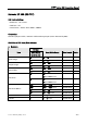
b. Contacts
Format
Type
Word No.(n)
Bank No.(m)
Bit No.(b)
Read/Write Range Note
Input Image In.b I0.0 - I65535.7
Output Image Qn.b Q0.0 - Q65535.7
Internal Bits Mn.b M0.0 - M65535.7
Data Area DBm.DBXn.b DB1.DBX0.0 – DB255.DBX65535.7
DBXn.b DBX0.0 – DBX65535.7
Data Area (DB10)
Vn.b V0.0 – V65535.7
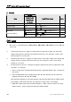
NOTE
1) PLC needs to enable DB memory (DBm.DBWn、DBm.DBDn、DBm.DBXn.b) before DB data
can be read.
2) Timer reads only up to 3 digits. If a value input is more than 3 digits, the Timer will
regards the highest 3 (decimal) and replace the rest by 0. For example, a value 12345
will be written as 12300 in PLC.
3) Counter reads only up to 3 digits. If a value input is more than 3 digits, the Counter will
regards the first 3 digits and leave out the rest. For example, a value 12345 will be
written as 123 in PLC.
4) Except register Tn and Cn,data type of register is Byte and its order is opposite to usual
controller , for example :
1、 IW3 is a word which combined from IB3 and IB4,High Byte of IW3 is IB3;Low Byte of
IW3 is IB4.
2、 ID3 is Double Word which combined from IB3, IB4, IB5 and IB6, and its order from
highest to lowest is IB3, IB4, IB5 andIB6.
And please be attentive to use these registers, because their Data type is different with
Data Length, it will need more than one register for each access, for example:
1、 AIW6 which Data Type is Byte and Data Length is 1 Word, when it used for one word
Numeric Entry , it will occupy two addresses AIB6 and AIB7。
204 V1.02 Revision January, 2012