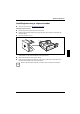
System expansions Installing/removing a chipcard reader Open the system unit (see "Opening the system unit"). Installing a chipcard reader Remove the protector panel at the front of the carrier. Push the chipcard reader board into the guide rail of the carrier with the component's side toward the panel. Fix the board with the screw.
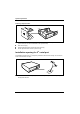
System expansions Removing a chipcard reader 4 2 3 1 Pull the cable off the chipcard reader (1) and off the connector for the chipcard reader on the system board (see the Technical Manual of the system board). Press on the clip (2). Pull the chipcard reader in the direction of the arrow (3). Lift the chipcard reader out of the system unit (4). Installation opening for 2nd serial port An installation opening for the 2nd serial port is provided on the back of the casing.
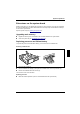
System expansions Extensions on the system board Details of how and if you can upgrade the main memory or the processor of your PC are provided in the Technical Manual for the system board. Below the necessary steps are described to enable you to work on the system board. Open the system unit (see „Opening the system unit“). Upgrading main memory Upgrade the memory as it is described in the Technical Manual for the system board. Close the system unit (see "Assembling the system unit").
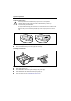
System expansions Replacing lithium battery ! Incorrect replacement of the lithium battery may lead to a risk of explosion. The lithium battery may be replaced only with an identical battery or with a type recommended by the manufacturer. Do not throw lithium batteries into the trashcan. It must be disposed of in accordance with local regulations concerning special waste. Make sure that you insert the battery the right way round.
Technical data Electrical data Regulations complied with: EN 60950 / VDE 0805 UL 1950 CSA 22.2 No.950 Protection class: I Rated voltage range: (selectable) 100 V to 125 V / 200 V to 240 V Frequency: 50 Hz - 60 Hz Max. rated current • System unit with monitor socket: • Monitor socket (output) 100 V -125 V/5.5 A 200 V -240 V/3.0 A 100 V -125 V/3 A 200 V -240 V/1.
Technical data Environmental conditions Environment class (3K2) Environment class (2K2) DIN IEC 721 part 3-3 DIN IEC 721 part 3-2 Temperature: • Operating (3K2) • Transport (2K2) 15 °C .... 35 °C -25 °C .... 60 °C Condensation in operating must be avoided. Clearance required to ensure adequate ventilation: left-hand side min. 200 mm front min. 200 mm rear min. 200 mm • • • ! 46 Do not place several system units one above the other.
Index 2 2nd serial port, installation opening 42 A Accessible drive installing 34 removing 36 Accumulator, disposal 4 Activating, security measures 23 Alphanumeric keypad 20 Alt Gr key 21 Anti-theft protection 24 Assembling, PC 30 Audio input 11 Audio output 11 B Battery 44 disposal 4 BIOS Setup 23 security functions 24 Board 3 installing 31 removing 31 C Cable connecting 10 disconnecting 10 Cabling, PC 10 Calculator keypad 20 Casing assembling 30 opening 29 Casing lock 15 CD-ROM drive indicator 19 installi
Index indicator 20 Class B Compliance Statement 5 Cleaning 8 Clearance 46 Configuration, BIOS-Setup 23 Connecting cables 10 devices 10 keyboard 12 monitor 13 mouse 12 parallel port 12 power voltage 14 serial port 12 Connecting to power voltage 14 Contents of delivery 9 Control key 21 Courier 1 Ctrl key 21 Ctrl+Alt+Del 21 Cursor control keys 20 D Dark screen 26 Data protection 23 Data, technical 45 Date, not correct 27 Devices connecting 10 interface 11 Dimensions 45 Diskette 22 write-protection 22 Display,
Index time 27 Error message 27 ESD 3 Euro key 21 Expansion 29 External devices connecting 10 ports 11 F FCC statement 5 First time, switching on 17 Flashing power-on indicator 19 Floppy disk drive changing 37 indicator 20 removing 36 Floppy disk, cannot be read or written 27 Function keys 20 G Game port 11 Green, power-on indicator 19 Guarantee coupon booklet 9 H Hard disk carrier installing 40 removing 38 Hard disk drive installing 35 replacing 38 Hard disk indicator 19 I IDE drives 33 Important notes 3 I
Index K Kensington Lock 24 Key combination 21 Keyboard 20 cleaning 8 connecting 12 Keyboard port 11 Keys 21 L LAN-port 11 Lead-sealing 24 Line in 11 Line out 11 Lithium battery 43 replacing 44 Lock 15 Locking, PC 15 M Main memory 43 Main switch 16 Manuals, further 28 Manufacturer’s notes 4 Memory, upgrading 43 Menu key 21 Message indicator 19 Microphone jack 11 Monitor connecting 13 transporting 7 Monitor port 11 Mouse cleaning 8 connecting 12 error 27 Mouse port 11 N New Installation, Software 25 No scree
Index Numeric keypad 20 O ON/OFF switch 16, 21 Opening, system unit 29 Operation 9 Orange, power-on indicator 19 Other manuals 28 Overview PC 1 preparing for use 9 P Packing material 9 Parallel port 11 connecting devices 12 PC cabling 10 cannot boot 25 cleaning 8 closing 30 connecting 10 connecting to power voltage 14 indicators 19 locking 15 opening 29 ports 11 setting up 10 switching off 16, 18 switching on 16, 18 switching on for the first time 17 transporting 7 unlocking 15 Ports, external devices 11 P
Index Reinstalling, hard disk contents 28 Removing accessible drive 36 board 31 hard disk carrier 38 hard disk drive 39, 40 ventilation duct 43 Replacing board 31 hard disk drive 38 lithium battery 44 Restoring, hard disk contents 28 Return key 21 S Safety 3 Screen blank 17, 18, 26 Screen blanking 4 SCSI drives 33 SCSI port 11 Security function 24 Security functions casing lock 23 Chipcard 23 MS-Windows 23 Security measures 23 Select, power cord 6 Serial port 11 connecting devices 12 Setting, rated voltage
Index Trouble floppy 27 mouse 27 screen 26 System unit 25 Troubleshooting 25 U Unlocking, PC 15 Unpacking 9 Upgrading, memory 43 USB, Universal Serial Bus 11 V Ventilation area 46 Ventilation duct installing 44 removing 43 VESA (DPMS) 4 Video workstation 10 W Warm boot 21 Weight 45 Winter time 27 Write protection, floppy 22 A26361-K520-Z100-4-7619 53