AIR CONDITIONER Wall mounted type SERVICE MANUAL INDOOR ASUG09LZAS ASUG12LZAS ASUG15LZAS OUTDOOR AOUG09LZAH1 AOUG12LZAH1 AOUG15LZAH1 SR_AS025EF_04 2020.02.
Notices: • Product specifications and design are subject to change without notice for future improvement. • For further details, please check with our authorized dealer. Trademarks FGLair™ is trademark of Fujitsu General Limited in the United States, other countries or both. Google Play™ is trademark of Google Inc. App Store® is a service mark of Apple Inc., registered in the U.S. and other countries. Copyright © 2020 Fujitsu General Limited. All rights reserved.
CONTENTS 1. GENERAL INFORMATION 2. TECHNICAL DATA AND PARTS LIST 3. TROUBLESHOOTING 4. CONTROL AND FUNCTIONS 5.
1. GENERAL INFORMATION 2020.01.
CONTENTS 1. GENERAL INFORMATION 1. Specifications..............................................................................................01-1 1-1. Indoor unit ......................................................................................................................01-1 1-2. Outdoor unit....................................................................................................................01-3 2. Dimensions.......................................................................
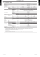
GENERAL INFORMATION GENERAL INFORMATION 1. Specifications 1-1. Indoor unit Wall mounted Type Inverter heat pump Model name ASUG09LZAS Power supply Power supply intake Available voltage range 208/230 V ~ 60 Hz Outdoor unit 187—253 V 2.64 3.52 4.25 9,000 12,000 14,500 0.91—3.52 0.91—3.99 0.91—5.39 3,100—12,000 3,100—13,600 3,100—18,400 3.52 4.69 5.28 12,000 16,000 18,000 0.91—6.45 0.91—6.48 0.91—7.00 3,100—22,000 3,100—22,100 3,100—23,900 2.17 2.93 3.28 7,400 10,000 11,200 4.69 5.13 6.
Inverter heat pump Model name ASUG09LZAS ASUG12LZAS ASUG15LZAS NOTES: • Specifications are based on the following conditions: – Cooling: Indoor temperature of 80 °FDB (26.67 °CDB) /67 °FWB (19.44 °CWB), and outdoor temperature of 95 °FDB (35 °CDB) / 75 °FWB (23.9 °CWB). – Heating: Indoor temperature of 70 °FDB (21.11 °CDB) /59 °FWB (15.56 °CWB), and outdoor temperature of 47 °FDB (8.33 °CDB) /43 °FWB (6.11 °CWB). – *1: Heating (17 °F): Indoor temperature of 70 °FDB (21.11 °CDB) /60 °FWB (15.
Type Inverter heat pump Model name AOUG09LZAH1 Power supply Available voltage range Starting current Airflow rate Fan A Cooling Heating Type × Q'ty Motor output Sound pressure level *1 CFM (m3/h) W Cooling Heating Dimensions (H × W × D) Fin pitch dB (A) in (mm) FPI Rows × Stages Heat exchanger type Pipe type Fin type Compressor Type Motor output Type (Material) Surface treatment W Type Refrigerant Refrigerant oil Enclosure Dimensions (H × W × D) Weight Operation range lb oz g Type Amount
GENERAL INFORMATION 2-1. Indoor unit ¢ Models: ASUG09LZAS, ASUG12LZAS, and ASUG15LZAS Unit: in (mm) 9-7/16 (240) 11 (280) 38-9/16 (980) 3-1/16 (77) 16-1/4 (413) 15-3/4 (400) 3-9/16 (90) for pipe inlet Ø 2-9/16 (65) 2-3/8 (61) 2-1. Indoor unit 1-7/16 (37) Outline of indoor unit 1-7/16 (37) GENERAL INFORMATION 2. Dimensions 16-7/8 (429) for pipe inlet Ø 2-9/16 (65) 4-1/2 (115) 2-13/16 (72) 16-7/16 (417) - (01-4) - 2-7/8 (73) 2.
Unit: in (mm) 3 (71) or more 2 (40) or more 5 (117) or more Wall hook bracket Outline of the indoor unit 3 (70) or more 7 (160) or more 71 (1,800) or more 60 (1,500) or more 2-1. Indoor unit - (01-5) - 2. Dimensions GENERAL INFORMATION Provide sufficient installation space for product safety.
13 (330) 4-M10 hole 22-13/16 (580) Pitch of bolts for installation 13-7/8 (353) Unit: in (mm) 4-5/16 (109) Pitch of bolts for installation Top view 3/4 (19) 31-7/16 (799) 2-11/16 (68) 1/2 (13) 11-7/16 (290) 13/16 (20) 1-5/16 (33) Side view 1-3/16 (30) Side view Front view Hole 1-7/16 (37) Hole 4-1/4 (184) 4-3/4 (120) Airflow Hole 15-11/16 (399) 7-1/16 (180) Drain port Ø1-5/8 (42) Bottom view 2-2. Outdoor unit - (01-6) - Side view (Valve part) 2.
2. TECHNICAL DATA AND PARTS LIST 2020.01.
CONTENTS 2. TECHNICAL DATA AND PARTS LIST 1. Precautions..................................................................................................02-1 2. Indoor unit parts list....................................................................................02-2 2-1. Models: ASUG09LZAS, ASUG12LZAS, and ASUG15LZAS..........................................02-2 3. Outdoor unit parts list.................................................................................02-6 3-1.
1. Precautions CAUTION • Service personnel – Any person who is involved with working on or breaking into a refrigerant circuit should hold a current valid certificate from an industry-accredited assessment authority, which authorizes their competence to handle refrigerants safely in accordance with an industry recognized assessment specification. – Servicing shall only be performed as recommended by the equipment manufacturer.
2. Indoor unit parts list TECHNICAL DATA AND PARTS LIST TECHNICAL DATA AND PARTS LIST 2-1. Models: ASUG09LZAS, ASUG12LZAS, and ASUG15LZAS ¢ Exterior parts and Accessories 1 19 20 17 a b 2 2 3 16 4 5 18 15 6 d c 7 8 15 9 14 8 10 13 11 12 2-1. Models: ASUG09LZAS, ASUG12LZAS, and ASUG15LZAS - (02-2) - 2.
Part no. 1 2 3 4 5 6 7 8 9 10 11 12 13 14 15 16 17 18 19 20 a b c d 9323351004 9387476002 9313951047 9387597035 9383765032 9383634017 9387479010 9332911008 9323341005 9317250009 9332438765 9318912005 9387596441 9387756210 9323340008 9333719009 9333704005 9323342002 9383730023 9333608006 — — — — 2-1.
¢ Chassis 50 a 51 b 52 TECHNICAL DATA AND PARTS LIST TECHNICAL DATA AND PARTS LIST 53 70 54 56 68 69 c 66 55 67 57 65 60 58 62 64 d 61 e 63 59 2-1. Models: ASUG09LZAS, ASUG12LZAS, and ASUG15LZAS - (02-4) - 2.
TECHNICAL DATA AND PARTS LIST 50 51 52 53 54 55 56 57 58 59 60 61 62 63 64 65 66 67 68 69 70 a b c d e Part no. 9383735042 9383735059 9387467000 9306489045 9711141392 9711141408 9711141415 9900627041 9711146014 9317755061 9387589023 9603821005 9383565007 9387488043 9387714012 9383728006 9387590036 9316904002 9316177017 9387591019 9383727009 9333628004 9387055054 9387587029 — — — — — 2-1.
3-1. Models: AOUG09LZAH1, AOUG12LZAH1, and AOUG15LZAH1 TECHNICAL DATA AND PARTS LIST TECHNICAL DATA AND PARTS LIST 3. Outdoor unit parts list ¢ Exterior parts and chassis 1 25 b 24 22 2 23 21 3 9 8 4 7 10 5 6 11 12 20 a 19 13 18 16 14 15 17 3-1. Models: AOUG09LZAH1, AOUG12LZAH1, and AOUG15LZAH1 - (02-6) - 3.
Part no. 1 2 3 4 5 6 7 8 9 10 11 12 9322556028 9377854001 9322327000 9322552242 9384276001 9322570062 9901059025 9323540019 9323541016 9383720000 9323550025 9322144003 9709684009 9709684016 9709684023 9900935054 9900985011 9900565060 9322420039 9810028006 9317903011 9384273000 9322555182 9322150004 9603601003 9322553027 9317089616 9317089654 — — 13 14 15 16 17 18 19 20 21 22 23 24 25 a b 3-1.
¢ Compressor 52 51 TECHNICAL DATA AND PARTS LIST TECHNICAL DATA AND PARTS LIST A B 50 a 53 B b 54 A 55 56 61 3-1. Models: AOUG09LZAH1, AOUG12LZAH1, and AOUG15LZAH1 60 59 - (02-8) - 58 57 3.
TECHNICAL DATA AND PARTS LIST 50 51 52 53 54 55 56 57 58 59 60 61 a b Part no. 9810542007 9810541000 9322446015 9970194023 9970173028 9322463029 9322474001 9322850010 9387831016 9322824004 9323045002 9322501004 9322847003 9322503008 — — 3-1.
4. Accessories TECHNICAL DATA AND PARTS LIST TECHNICAL DATA AND PARTS LIST 4-1. Indoor unit ¢ Models: ASUG09LZAS, ASUG12LZAS, and ASUG15LZAS 4-2. Outdoor unit ¢ Models: AOUG09LZAH1, AOUG12LZAH1, and AOUG15LZAH1 Part name Installation manual 4-1. Indoor unit Exterior Q’ty 1 Part name Cable tie - (02-10) - Exterior Q’ty 2 4.
5. Optional parts ¢ Controllers Exterior Office Model name Fri 10:00AM Mode Custom Auto Away Part name Cool Heat Set Temp. Cool Heat 84°F 68°F 80°F 74°F Fan Auto Room Temp. 76°F Vacation Status Menu Wired remote controller UTY-RNRUZ* Summary Easy finger touch operation with LCD panel. Backlit LCD enables easy operation in a dark room. Wire type: Non-polar 2-wire Optional communication kit is necessary for installation.
¢ Others Part name TECHNICAL DATA AND PARTS LIST External connect kit 5-1. Indoor unit Model name Summary Required when external device is UTY-XWZXZ5 connected. External input and output PCB UTY-XCSXZ2 Use to connect with external devices and air conditioner PCB. Optional External connect kit is necessary for installation. Communication kit UTY-TWRXZ2 Use to connect Non-polar 2-core wired remote controller.
TECHNICAL DATA AND PARTS LIST 6-1. Models: AOUG09LZAH1, AOUG12LZAH1, and AOUG15LZAH1 Heat exchanger (INDOOR) 3-way valve ThPI 2-way valve Muffler Th R Muffler Th D Compressor TECHNICAL DATA AND PARTS LIST 6.
7. Wiring diagrams TECHNICAL DATA AND PARTS LIST TECHNICAL DATA AND PARTS LIST 7-1. Indoor unit ¢ Models: ASUG09LZAS, ASUG12LZAS, and ASUG15LZAS 7-2. Outdoor unit ¢ Models: AOUG09LZAH1, AOUG12LZAH1, and AOUG15LZAH1 7-1. Indoor unit - (02-14) - 7.
8. PC board diagrams TECHNICAL DATA AND PARTS LIST TECHNICAL DATA AND PARTS LIST 8-1. Models: ASUG09LZAS, ASUG12LZAS, and ASUG15LZAS CONTROL UNIT ASUG09LZAS : EZ-0190EHSE ASUG12LZAS : EZ-0190FHSE ASUG15LZAS : EZ-0190GHSE 2-WIRE REMOTE CONTROL UNIT ( OPTION ) UTY-TWRXZ2 1 2 3 4 5 6 CN13 B07B-PASK-1 WHITE DC5V DC12V CN5 DC Fan motor Pin No.
8-2.
3. TROUBLESHOOTING 2020.01.
CONTENTS 3. TROUBLESHOOTING 1. Error code ....................................................................................................03-1 1-1. Error code table (Indoor unit and wired remote controller)..............................................03-1 1-2. Error code table (Wireless LAN indicator).......................................................................03-2 1-3. Error code table (Mobile app) .........................................................................................
CONTENTS (continued) 4-4. E: 18. Communication error..........................................................................................03-55 4-5. E: 18. Wireless LAN adapter non-energized.................................................................03-57 4-6. Wireless LAN adapter Sleep mode (Indoor unit) ..........................................................03-58 4-7. Mobile app setting method............................................................................................03-59 5.
1. Error code 1-1. Error code table (Indoor unit and wired remote controller) TROUBLESHOOTING Indoor unit display Error contents E: 11. Serial communication error (Serial reverse transfer error) (Outdoor unit) E: 11. Serial communication error (Serial forward transfer error) (Indoor unit) E: 12. Wired remote controller communication error (Indoor unit) E: 18. External communication error (Indoor unit) E: 18. External communication error between indoor unit and WLAN adapter E: 18.
1-2. Error code table (Wireless LAN indicator) • Wireless LAN control system diagram example Indoor unit Internet Controller PCB Cloud Mobile app (Smart device) TROUBLESHOOTING Outdoor unit TROUBLESHOOTING Wireless LAN router Parts: WLAN adapter • Name of parts Wireless LAN adapter Wireless LAN label MAC: SSID: AP-WF PIN: Connection port • Wireless LAN indicator For confirmation of the error contents, refer the flashing pattern as follows.
1-3. Error code table (Mobile app) • Error display If there is an abnormality on the air conditioning, refer to as follows. When the (error button) on the home screen is tapped, error code and error name is displayed. – For Android TROUBLESHOOTING TROUBLESHOOTING Error button Error code Error Name – For iOS Error button Error code Error Name 1-3. Error code table (Mobile app) - (03-3) - 1.
• Error code Error contents Error code 11.1 11.2 11.3 11.4 Outdoor unit main PCB model information error E: 11. Serial communication error (Serial reverse transfer error) (Outdoor unit) E: 11. Serial communication error (Serial forward transfer error) (Indoor unit) E: 12. Wired remote controller communication error (Indoor unit) E: 32. Indoor unit main PCB error (Indoor unit) E: 35. MANUAL AUTO button error (Indoor unit) E: 41. Room temperature sensor error (Indoor unit) E: 42.
1-4. Error message for wireless LAN control (Mobile app) • Error display If there is an abnormality on the wireless control system, refer to error messages as follows. The error message disappears after 5 seconds and the normal screen is displayed. For iOS Error message 1-4. Error message for wireless LAN control (Mobile app) - (03-5) - TROUBLESHOOTING TROUBLESHOOTING For Android Error message 1.
• Error message list – For Android Error message Cause Wi-Fi must be enabled to set up new device We weren’t able to sign you onto null. Please goto the WiFi settings and join the network from there. Return to the app when you’re done. Could not connect to the device at this time. Please reset the device and try again. The user has disabled Wi-Fi on the smart device. The smart device and air conditioner are connected to difference Wi-Fi networks when attempting to register.
General error TROUBLESHOOTING Cause The smart device has no internet access. Solution Connect the mobile device to the internet. The router the air conditioner Check if the router connected to the air is connected to, has no conditioner has internet access. (You can internet access. check by connecting the mobile device to the router, then opening the website.) If there is no access, connect the router to the internet.
Registration error Cause Solution General error Error message Cause Failed to change password. The smart device has no Cloud not determine service internet access. reachability. Failed to update property. Could not retrieve schedules. The operation couldn’t be completed. Operation timed out. “Device name” is offline. (Device name varies depending on the air conditioner) Solution Connect the mobile device to the internet. Check if the router connected to the air conditioner has internet access.
2. Troubleshooting with error code Indicator Indoor unit Detective actuator Outdoor unit Forecast of cause Operation indicator 1 time flash Timer indicator 1 time flash Economy indicator Continuous flash Error code E: 11 Main PCB When the indoor unit cannot receive the serial signal from outdoor unit more than 2 minutes after power on, or the indoor unit cannot receive the serial signal more Fan motor than 15 seconds during normal operation.
Check point 4. Check serial signal (Reverse transfer signal) Check serial signal (Reverse transfer signal) • • • • WHITE N BLACK L RED 3 WHITE 2 BLACK 1 + - Check if indicated value swings between AC 90 V and AC 270 V at the outdoor unit terminal 1 —3. If it is abnormal, check the parts below. – Outdoor unit fan motor in "Service parts information" on page 03-64 If outdoor fan motor is abnormal, replace outdoor unit fan motor and main PCB. If the checked parts are normal, replace the main PCB.
Indicator Indoor unit Detective actuator Indoor unit Forecast of cause Operation indicator 1 time flash Timer indicator 1 time flash Economy indicator Continuous flash Error code E: 11 Main PCB When the outdoor unit cannot receive the serial signal from indoor unit more than 10 seconds. Fan motor Connection failure External cause Main PCB failure Indoor unit fan motor failure Check point 1. Reset the power and operate Does error indication show again? → If no, go to "Check point 1-2". ↓ Check point 2.
Check point 4. Check serial signal (reverse transfer signal) Check serial signal (Forward transfer signal) • • • • WHITE N BLACK L RED 3 WHITE 2 BLACK 1 + - Check if indicated value swings between AC 30 V and AC 130 V at outdoor unit terminal 2—3. If it is abnormal, replace main PCB. If it is abnormal, check indoor unit fan motor. (Indoor unit fan motor in "Service parts information" on page 03-64) If indoor unit fan motor is abnormal, replace indoor unit fan motor and main PCB.
Indicator TROUBLESHOOTING Detective actuator Forecast of cause Operation indicator 1 time flash Timer indicator 2 time flash Indoor unit Economy indicator Continuous flash Error code E: 12 Indoor unit Main PCB When the indoor unit cannot receive the signal from Wired remote controller more than 1 minute during Wired remote control normal operation. Terminal connection abnormal Wired remote control failure Main PCB failure Check point 1.
Indicator Indoor unit Detective actuator Indoor unit Forecast of cause Operation indicator 1 time flash Timer indicator 8 time flash Economy indicator Continuous flash Error code E: 18 External After receiving a signal from the external input and communication output PCB, the same signal has not been received for error 15 seconds. Connection failure External input and output PCB failure Main PCB Check point 1.
Indicator Indoor unit Operation indicator Timer indicator Economy indicator Error code Detective actuator Indoor unit main PCB Forecast of cause 3 time flash 2 time flash Continuous flash E: 32 When power is on and there is some below case. 1. When model information of EEPROM is incorrect. 2. When the access to EEPROM failed. External cause Defective connection of electric components Main PCB failure Check point 1.
Indicator TROUBLESHOOTING Detective actuator Forecast of cause Operation indicator 3 time flash Timer indicator 5 time flash Indoor unit Economy indicator Continuous flash Error code E: 35 Indoor unit controller PCB When the MANUAL AUTO button becomes on for Indicator PCB consecutive 30 or more seconds. Manual auto switch MANUAL AUTO button failure Controller PCB and indicator PCB failure Check point 1. Check the MANUAL AUTO button • • Check if MANUAL AUTO button is kept pressed.
Indicator TROUBLESHOOTING Detective actuator Forecast of cause Operation indicator 4 time flash Timer indicator 1 time flash Indoor unit Economy indicator Continuous flash Error code E: 41 Indoor unit main PCB Room temperature thermistor is open or short is detected always. Room temperature thermistor Connector failure Thermistor failure Main PCB failure Check point 1. Check connection of connector • • • Check if connector is loose or removed. Check erroneous connection.
Indicator TROUBLESHOOTING Detective actuator Forecast of cause Operation indicator 4 time flash Timer indicator 2 time flash Indoor unit Economy indicator Continuous flash Error code E: 42 Indoor unit main PCB When heat exchanger temperature thermistor open or Heat exchanger temperature short circuit is detected. thermistor Connector connection failure Thermistor failure Main PCB failure Check point 1. Check connection of connector • • • Check if connector is loose or removed.
Indicator Indoor unit Detective actuator Indoor unit Forecast of cause Operation indicator 5 time flash Timer indicator 1 time flash Economy indicator Continuous flash Error code E: 51 main PCB When the condition that actual frequency of indoor fan is below 1/3 of target frequency is continued more than 56 Fan motor seconds. Fan rotation failure Fan motor winding open Motor protection by surrounding temperature rise Control PCB failure Indoor unit fan motor failure Check point 1.
Indicator TROUBLESHOOTING Detective actuator Forecast of cause Operation indicator 5 time flash Timer indicator 8 time flash Indoor unit Economy indicator Continuous flash Error code E: 58 Indoor unit main PCB When the Micro switch is detected open while running the compressor. Micro switch Micro switch failure Shorted connector/wire Main PCB failure Check point 1. Check limit switch • • Check operation of Micro switch. (any blocking by dust, etc.
2-11. E: 62. Outdoor unit main PCB error (Outdoor unit) Indoor unit Detective actuator Outdoor unit Main PCB TROUBLESHOOTING Forecast of cause Check point 1. Reset power supply and operate Does error indication show again? 6 time flash 2 time flash Continuous flash E: 62 Access to EEPROM failed due to some cause after outdoor unit started.
Indicator Indoor unit Detective actuator Forecast of cause Outdoor unit Operation indicator 6 time flash Timer indicator 3 time flash Economy indicator Continuous flash Error code E: 63 Inverter PCB Error information received from inverter PCB External cause Power supply to inverter PCB wiring disconnection or open Inverter PCB failure Check point 1. Turn the power on again? If no, go to "Check point 1-2". Error displayed again? ↓ Check point 2.
Indicator Indoor unit Operation indicator Timer indicator Economy indicator Error code • TROUBLESHOOTING Detective actuator Outdoor unit Main PCB • Forecast of cause 6 time flash 4 time flash Continuous flash E: 64 When inverter input DC voltage is higher than 415 V for over 3 seconds, the compressor stops. If the same operation is repeated 5 times, the compressor stops permanently. External cause Connector connection failure Main PCB failure Check point 1.
Indicator TROUBLESHOOTING Detective actuator Forecast of cause Operation indicator 7 time flash Timer indicator 1 time flash Indoor unit Economy indicator Continuous flash Error code E: 71 Outdoor unit main PCB When discharge pipe temperature thermistor open or short circuit is detected at power on or while running the Discharge pipe temperature compressor thermistor Connector failure Thermistor failure Main PCB failure Check point 1.
Indicator TROUBLESHOOTING Detective actuator Forecast of cause Operation indicator 7 time flash Timer indicator 3 time flash Indoor unit Economy indicator Continuous flash Error code E: 73 Outdoor unit main PCB When heat exchanger temperature thermistor open or short circuit is detected at power on or while running the Heat exchanger temperature compressor thermistor Connector failure Thermistor failure Main PCB failure Check point 1.
Indicator TROUBLESHOOTING Detective actuator Forecast of cause Operation indicator 7 time flash Timer indicator 4 time flash Indoor unit Economy indicator Continuous flash Error code E: 74 Outdoor unit main PCB When outdoor temperature thermistor open or short circuit is detected at power on or while running the Outdoor temperature thermistor compressor Connector failure Thermistor failure Main PCB failure Check point 1. Check connection of connector • • • Check if connector is loose or removed.
Indicator Indoor unit Operation indicator Timer indicator Economy indicator Error code Detective actuator Outdoor unit main PCB Forecast of cause Check point 1. Reset power supply and operate Does error indication show again? 8 time flash 4 time flash Continuous flash E: 84 When input current sensor has detected 0 A, while inverter compressor is operating at higher than 56 rps, after 1 minute upon starting the compressor.
Indicator Indoor unit Detective actuator Outdoor unit Forecast of cause Operation indicator 9 time flash Timer indicator 4 time flash Economy indicator Continuous flash Error code E: 94 Main PCB Protection stop by over-current generation after inverter compressor start processing completed generated consecutively 10 times. Compressor NOTE: The number of generations is reset when the compressor starts up.
Indicator Indoor unit Detective actuator Outdoor unit Operation indicator Timer indicator Economy indicator Error code Main PCB Compressor Forecast of cause 9 time flash 5 time flash Continuous flash E: 95 1. When running the compressor, if the detected rotor location is out of phase with actual rotor location more than 90°, the compressor stops. 2. After the compressor restarts, if the same operation is repeated within 40 seconds, the compressor stops again. 3. If 1. and 2.
Indicator Indoor unit Detective actuator Outdoor unit Operation indicator Timer indicator Economy indicator Error code Main PCB Fan motor Forecast of cause 9 time flash 7 time flash Continuous flash E: 97 1. When outdoor fan rotation speed is less than 100 rpm in 20 seconds after fan motor starts, fan motor stops. 2. After fan motor restarts, if the same operation within 60 seconds is repeated 3 times in a row, compressor and fan motor stops. 3. If 1. and 2.
Check point 4. Check output voltage of main PCB Check outdoor unit circuit diagram and the voltage. (Measure at main PCB side connector) RED FAN MOTOR BLACK WHITE YELLOW BROWN FM TROUBLESHOOTING TROUBLESHOOTING 1 2 3 4 5 6 7 NOTE: For details of wiring diagram, refer to "Wiring diagrams" in Chapter 2. TECHNICAL DATA AND PARTS LIST on page 02-14. Read wire DC voltage Red—Black 240 V — 400 V White—Black 13.5 V — 16.5 V -> If the voltage is not correct, replace Main PCB. ↓ End 2-20. E: 97.
TROUBLESHOOTING Indicator Operation indicator Timer indicator Indoor unit Economy indicator Error code Indoor unit main PCB Heat exchanger temperature thermistor Room temperature thermistor Detective actuator 4-way valve Forecast of cause 9 time flash 9 time flash Continuous flash E: 99 When the indoor heat exchanger temperature is compared with the room temperature, and either following condition is detected continuously two times, the compressor stops. Indoor heat exchanger temp. - Room temp.
Check point 3. Check the solenoid coil and 4-way valve TROUBLESHOOTING • Solenoid coil Remove CN30 from PCB and check the resistance value of coil. Resistance value is 1.88 kΩ — 2.29 kΩ (at 68 °F (20 °C)). → If it is open or abnormal resistance value, replace solenoid coil. 4-way valve Check each piping temperature, and the location of the valve by the temperature difference. If the value location is not proper, replace 4-way valve. ↓ Check point 4.
Indicator TROUBLESHOOTING Detective actuator Forecast of cause Operation indicator 10 time flash Timer indicator 1 time flash Indoor unit Economy indicator Continuous flash Error code E: A1 Outdoor unit main PCB Protection stop by discharge temperature ≥ 230 °F (110 °C) during compressor operation generated 2 times Discharge temperature thermistor within 24 hours.
Check point 5. Check the refrigerant amount Check the refrigerant leakage. ↓ Check point 6. Replace main PCB If check point 1 to 5 do not improve the symptom, replace the main PCB. TROUBLESHOOTING TROUBLESHOOTING ↓ End 2-22. E: A1. Discharge temperature error (Outdoor unit) - (03-35) - 2.
3. Troubleshooting without error code 3-1. Indoor unit—No power TROUBLESHOOTING Forecast of cause Check point 1. Check installation condition • • Isn’t the breaker down? Check loose or removed connection cable. -> If abnormal condition is found, correct it by referring to the installation manual or the “DESIGN & TECHNICAL MANUAL”. ↓ Check point 2.
3-2. Outdoor unit—No power Power supply failure External cause Electrical components defective Forecast of cause • • Isn’t the breaker down? Check loose or removed connection cable. → If abnormal condition is found, correct it by referring to the installation manual or the “DESIGN & TECHNICAL MANUAL”. ↓ Check point 2. Check external cause at indoor and outdoor (voltage drop or noise) • • • Instant drop: Check if there is a large load electric apparatus in the same circuit.
3-3. No operation (Power is on) Setting/ Connection failure External cause Electrical components defective Forecast of cause TROUBLESHOOTING • • Indoor unit: – Check incorrect wiring between indoor unit and remote controller. – Check if there is an open cable connection. Are these indoor unit, outdoor unit, and remote controller suitable model numbers to connect? -> If there is some abnormal condition, correct it by referring to the installation manual and “DESIGN & TECHNICAL MANUAL”.
3-4. No cooling/No heating Indoor unit error Outdoor unit error Effect by surrounding environment Connection pipe/Connection wire failure Refrigeration cycle failure Forecast of cause • • • • TROUBLESHOOTING TROUBLESHOOTING Check point 1. Check Indoor unit Does Indoor unit fan run in the HIGH mode? Is air filter dirty? Is heat exchanger clogged? Check if energy save function is operated. ↓ Check point 2. Check outdoor unit operation • • • • Check if outdoor unit is operating.
NOTES: • Strainer normally does not have temperature difference between inlet and outlet as shown below. Pipe (Out) • If there is a difference like shown below, there is a possibility of inside clogged. In this case, replace the strainer. Pipe (In) 3-4. No cooling/No heating Pipe (Out) - (03-40) - 3.
3-5. Abnormal noise Abnormal installation (indoor unit/outdoor unit) Fan failure (indoor unit/outdoor unit) Compressor failure (outdoor) Forecast of cause Abnormal noise is coming from Indoor unit. (Check and correct followings) Abnormal noise is coming from Indoor unit.
3-6.
3-7. Too warm House insulation setting has not been changed. Temperature sensing location has not been changed. Installation location of the wired remote. Function settings have not been changed. Forecast of cause Is insulation level greater than R-13? → If no, go to "Check Point 4". ↓ Check point 2. Check function setting If insulation level is greater than R-13 set function 95 to 01. NOTE: For details of function setting number 95, refer to "Function settings " in Chapter 5. FIELD WORKING on page 05-1.
Check point 6. Check the remote controller TROUBLESHOOTING TROUBLESHOOTING Hold down the THERMO SENSOR button until the thermo sensor icon is turned off. → If the space is still too warm, go to "Check point 7". ↓ End Check point 7. Check function settings Using the table on the right adjust function 31. (Room Temperature Control for indoor unit sensor) NOTE: For details of function setting number 31, refer to "Function settings " in Chapter 5. FIELD WORKING on page 05-1. ↓ End Check point 8.
Check point 10. Location of the remote controller Is the mounting location of the wired remote controller affecting the temperature sensing? (Sunlight on the remote, heat source next to the remote) → If no, go to "Check point 12". ↓ Move the remote controller. → If the space is still too warm, go to "Check point 12". TROUBLESHOOTING TROUBLESHOOTING Check point 11. Location of the remote controller ↓ End Check point 8-1.
Check point 9-1. Check function setting Change setting of function 48 (Room temperature sensor switching) to 01. NOTE: For details of function setting number 48, refer to "Function settings " in Chapter 5. FIELD WORKING on page 05-1. ↓ Did this function setting improve temperature control? → If the space is still too warm, go to "Check point 10". TROUBLESHOOTING TROUBLESHOOTING Check point 9-2. Check the effects of function setting change ↓ End Check point 12.
3-8. Too cool House insulation setting has not been changed. Temperature sensing location has not been changed. Installation location of the wired remote. Function settings have not been changed. Forecast of cause Is insulation level greater than R-13? → If no, go to "Check Point 4". ↓ Check point 2. Check function setting If insulation level is greater than R-13 set function 95 to 01. NOTE: For details of function setting number 95, refer to "Function settings " in Chapter 5. FIELD WORKING on page 05-1.
Check point 6. Check the remote controller TROUBLESHOOTING TROUBLESHOOTING Hold down the THERMO SENSOR button until the thermo sensor icon is turned off. → If the space is still too cool, go to "Check point 7". ↓ End Check point 7. Check function settings Using the table on the right adjust function 30. (Room Temperature Control for indoor unit sensor) NOTE: For details of function setting number 30, refer to "Function settings " in Chapter 5. FIELD WORKING on page 05-1. ↓ End Check point 8.
Check point 10. Location of the remote controller Is the mounting location of the wired remote controller affecting the temperature sensing? (Sunlight on the remote, heat source next to the remote) → If no, go to "Check point 12". ↓ Move the remote controller. → If the space is still too cool, go to "Check point 12". TROUBLESHOOTING TROUBLESHOOTING Check point 11. Location of the remote controller ↓ End Check point 8-1.
Check point 9-1. Check function setting Change setting of function 48 (Room temperature sensor switching) to 01. NOTE: For details of function setting number 48, refer to "Function settings " in Chapter 5. FIELD WORKING on page 05-1. ↓ Did this function setting improve temperature control? → If the space is still too cool, go to "Check point 10". TROUBLESHOOTING TROUBLESHOOTING Check point 9-2. Check the effects of function setting change ↓ End Check point 12.
4. Troubleshooting with error code (For wireless LAN adapter) TROUBLESHOOTING Indicator Operation indicator 1 time flash Timer indicator 8 time flash Indoor unit Economy indicator Continuous flash Error code E: 18 Flashing fast Wireless LAN LED1 (green) adapter LED2 (orange) On Wireless LAN adapter PCB After receiving a signal from the wireless LAN adapter, the same signal has not been received for 15 seconds.
4-2. Wireless LAN adapter error Detective actuator Setting button Wireless LAN adapter PCB Wireless LAN adapter setting button failure Wireless LAN adapter PCB failure Forecast of cause Check point 1. Check the setting button Check if setting button is kept pressed. -> If the setting button is held down by the foreign matter, remove the foreign matter or remove the cause of the button press. ↓ Check point 2. Replace wireless LAN adapter.
TROUBLESHOOTING Indicator Operation indicator No indication Timer indicator No indication Indoor unit Economy indicator No indication Error code — LED1 (green) On Wireless LAN adapter LED2 (orange) Flashing fast Wireless LAN router When the not connection between wireless LAN adapter and wireless LAN router.
Check point 4. Replace wireless LAN adapter. If check point 3 do not improve the symptom, replace the wireless LAN adapter and cancel the registration of air conditioner on the mobile app. After replacing the adapter, perform the pairing on the mobile app. For the method of the mobile app, refer to "Mobile app setting method" on page 03-59. End Check point 2-2. Check the transmission state Check the wireless transmission state pf the wireless LAN router (LED status).
TROUBLESHOOTING Indicator Operation indicator 1 time flash Timer indicator 8 time flash Indoor unit Economy indicator Continuous flash Error code E: 18 LED1 (green) Flashing fast Wireless LAN adapter LED2 (orange) Flashing fast Wireless LAN router When the external communication error between indoor unit and WLAN adapter and network communication Wireless LAN adapter PCB error between wireless LAN router and WLAN adapter has occurred simultaneously.
Check point 3-1. Turn on the power again of air conditioner. If check point 1 to 2 do not improve the symptom, turn on the power of the air conditioner again and wait for 60 seconds. -> When the flashing pattern of the LED 2 (orange) is on, go to "Check point 3-2". -> When the flashing pattern of the LED 2 (orange) is flashing fast, go to "Check point 4". ↓ • Check any loose or removed connection of between the wireless LAN adapter PCB and controller PCB. -> If there is abnormal condition, correct it.
Indicator TROUBLESHOOTING Detective actuator Forecast of cause Operation indicator 1 time flash Timer indicator 8 time flash Indoor unit Economy indicator Continuous flash Error code E: 18 LED1 (green) Off Wireless LAN adapter LED2 (orange) Off Indoor unit controller PCB When the voltage (DC 12 V) does not output from the controller PCB. Wireless LAN adapter PCB Indoor unit controller PCB failure Wireless LAN adapter PCB failure Wiring connection failure Check point 1. Check the connection.
Indoor unit Indicator Wireless LAN adapter TROUBLESHOOTING Detective actuator Operation indicator Timer indicator Economy indicator Error code LED1 (green) LED2 (orange) Sleep mode Forecast of cause No indication No indication No indication — Off Off When the state in which fly a wireless(SSID) have passed 1 hour. Sleep mode Check point 1. Cheak the sleep mode Press the Wireless LAN adapter setting button the 3 seconds or more.
4-7. Mobile app setting method ¢ Air conditioner deregistration method When the wireless LAN adapter is replaced, deregistration of all air conditioner is necessary on the mobile app. 1. Launch the mobile app. 2. Press and hold the registered device name of the air conditioner. 3. If the Unregister button is displayed, tap the button. 4. Tap the Yes button. 5. Deregstration of the air conditioner is completed. 4-7. Mobile app setting method - (03-59) - 4.
¢ Air conditioner registration pairing method NOTES: • Before starting this setting, wait for 60 seconds or more after the power supply is connected to the air conditioner (via breaker or plug). • Check that the smartphone or tablet PC is linked to the wireless router to be connected to the air conditioner. The setting does not work if the same wireless LAN router is not connected. • The displayed screen design may differ depending on the version of the mobile app.
6. Confirm LED 2 is flashing (On/Off at 2 seconds intervals). Then press and hold the setting button on the wireless LAN adapter for 3 seconds. on/off: 2 sec/2 sec LED 2 lighting will change. (On/Off: 2 sec./2 sec. → 2 sec./0.5 sec.) Confirm both of the LED 1 and 2 are on to proceed. 7. Press Register button to start the connection with the wireless LAN router. Register Registration Successful! 2 times Both of the LED 1 and 2 flash 2 times and a message appear when the setup is completed. 4-7.
Manual mode (For Android) 1. Launch the mobile app. FGL air 2. Sign in with your E-mail address and password following the screen on the mobile app. ÛÛÛÛÛÛ TROUBLESHOOTING TROUBLESHOOTING john@fgl.com Sign in 3. Press the + button to add a new air conditioner. + 4. Select manual mode. Button mode Manual mode If both of the LED 1 and 2 are off, push the setting button once. 5. Select the SSID of the air conditioner to be connected.
Manual mode (For iOS) 1. Launch the mobile app. FGL air 2. Sign in with your E-mail address and password following the screen on the mobile app. ÛÛÛÛÛÛ TROUBLESHOOTING TROUBLESHOOTING john@fgl.com Sign in 3. Press the + button to add a new air conditioner. + 4. Select manual mode. Button mode Manual mode If both of the LED 1 and 2 are off, push the setting button once. 5.
5. Service parts information 5-1. Compressor Diagnosis method of compressor (If outdoor unit LED displays error, refer to troubleshooting) ↓ Is there open or loose connection cable? ↓ Check main PCB, connection of compressor, and winding resistance. (Refer to the next page) → If there is no failure, the defect of compressor is considered (Locked compressor due to clogged dirt or less oil) ↓ Replace compressor.
5-2. Inverter compressor Check point 1. Check connection Check terminal connection of compressor. (loose or incorrect wiring) Terminal cover opened T(W) R(U) (RED) TROUBLESHOOTING TROUBLESHOOTING (BLACK) S(V) (WHITE) ↓ Check point 2. Check winding resistance Check winding resistance of each terminal. Resistance value: 1.916 Ω at 68 °F (20°C) C R S → If the resistance value is 0 Ω or infinite, replace compressor. ↓ Check point 3.
5-3. Outdoor unit Electronic Expansion Valve (EEV) Check point 1. Check connections Check point 2. Check coil of EEV TROUBLESHOOTING TROUBLESHOOTING Check connection of connector. (Loose connector or open cable) NOTE: For details of wiring diagram, refer to "Wiring diagrams" in Chapter 2. TECHNICAL DATA AND PARTS LIST on page 02-14. Remove connector, check each winding resistance of coil.
Check point 6. Check strainer Strainer normally does not have temperature difference between inlet and outlet as shown below. TROUBLESHOOTING Pipe (In) • Pipe (Out) If there is a difference like shown below, there is a possibility of inside clogged. In this case, replace the strainer. Pipe (In) 5-3. Outdoor unit Electronic Expansion Valve (EEV) Pipe (Out) - (03-67) - 5.
5-4. Indoor unit fan motor Check point 1. Check rotation of fan Check point 2. Check resistance of indoor fan motor Refer to below. Circuit-test “Vm” and “GND” terminal NOTE: Vm: DC voltage, GND: Earth terminal → If they are short-circuited (below 300 kΩ), replace indoor fan motor and controller PCB.
5-5. Outdoor unit fan motor Check point 1. Check rotation of fan Check point 2. Check resistance of outdoor fan motor Refer to below. Circuit-test “Vm” and “GND” terminal NOTE: Vm: DC voltage, GND: Earth terminal → If they are short-circuited (below 300 kΩ), replace outdoor fan motor and controller PCB.
6. Thermistor resistance values 6-1. Indoor unit Temperature °F (°C) Resistance (kΩ) Voltage (V) 14.0 (-10.0) 23.0 (-5.0) 32.0 (0.0) 41.0 (5.0) 50.0 (10.0) 59.0 (15.0) 68.0 (20.0) 77.0 (25.0) 86.0 (30.0) 95.0 (35.0) 104.0 (40.0) 113.0 (45.0) 58.25 44.03 33.62 25.93 20.18 15.84 12.54 10.00 8.04 6.51 5.30 4.35 0.73 0.93 1.15 1.39 1.66 1.94 2.22 2.50 2.77 3.03 3.27 3.49 ¢ Heat exchanger temperature thermistor 6-1. Indoor unit Temperature °F (°C) Resistance (kΩ) Voltage (V) -22.0 (-30.0) -13.0 (-25.
6-2. Outdoor unit 6-2. Outdoor unit Temperature °F (°C) Resistance (kΩ) Voltage (V) -22.0 (-30.0) -12.0 (-25.0) -4.0 (-20.0) 5.0 (-15.0) 14.0 (-10.0) 23.0 (-5.0) 32.0 (0.0) 41.0 (5.0) 50.0 (10.0) 59.0 (15.0) 68.0 (20.0) 77.0 (25.0) 86.0 (30.0) 95.0 (35.0) 104.0 (40.0) 113.0 (45.0) 122.0 (50.0) 131.0 (55.0) 140.0 (60.0) 149.0 (65.0) 158.0 (70.0) 167.0 (75.0) 176.0 (80.0) 185.0 (85.0) 194.0 (90.0) 203.0 (95.0) 212.0 (100.0) 221.0 (105.0) 230.0 (110.0) 239.0 (115.0) 248.0 (120.0) 1,013.11 729.09 531.
6-2. Outdoor unit Temperature °F (°C) Resistance (kΩ) Voltage (V) -22.0 (-30.0) -12.0 (-25.0) -4.0 (-20.0) 5.0 (-15.0) 14.0 (-10.0) 23.0 (-5.0) 32.0 (0.0) 41.0 (5.0) 50.0 (10.0) 59.0 (15.0) 68.0 (20.0) 77.0 (25.0) 86.0 (30.0) 95.0 (35.0) 104.0 (40.0) 113.0 (45.0) 122.0 (50.0) 131.0 (55.0) 140.0 (60.0) 149.0 (65.0) 158.0 (70.0) 167.0 (75.0) 176.0 (80.0) 185.0 (85.0) 194.0 (90.0) 203.0 (95.0) 212.0 (100.0) 221.0 (105.0) 230.0 (110.0) 239.0 (115.0) 248.0 (120.0) 1,013.11 729.09 531.56 392.31 292.91 221.
Temperature °F (°C) Resistance (kΩ) Voltage (V) -22.0 (-30.0) -12.0 (-25.0) -4.0 (-20.0) 5.0 (-15.0) 14.0 (-10.0) 23.0 (-5.0) 32.0 (0.0) 41.0 (5.0) 50.0 (10.0) 59.0 (15.0) 68.0 (20.0) 77.0 (25.0) 86.0 (30.0) 95.0 (35.0) 104.0 (40.0) 113.0 (45.0) 122.0 (50.0) 131.0 (55.0) 140.0 (60.0) 149.0 (65.0) 158.0 (70.0) 167.0 (75.0) 176.0 (80.0) 95.58 68.90 50.31 37.19 27.81 21.02 16.05 12.38 9.63 7.56 5.98 4.77 3.84 3.11 2.53 2.08 1.71 1.42 1.19 1.00 0.84 0.71 0.61 0.24 0.32 0.43 0.57 0.73 0.92 1.14 1.39 1.65 1.
TROUBLESHOOTING TROUBLESHOOTING 6-2. Outdoor unit - (03-74) - 6.
4. CONTROL AND FUNCTIONS 2020.02.
CONTENTS 4. CONTROL AND FUNCTIONS 1. Compressor frequency control..................................................................04-1 1-1. Cooling operation ...........................................................................................................04-1 1-2. Heating operation ...........................................................................................................04-3 1-3. Dry operation ......................................................................................
1. Compressor frequency control 1-1. Cooling operation A sensor (room temperature thermistor) built in the indoor unit body will usually perceive difference or variation between a set temperature and present room temperature, and controls the operation frequency of the compressor. • If the room temperature is 6.0 °C higher than a set temperature, the compressor operation frequency will attain to maximum performance. • If the room temperature is 1.
• Limit of maximum speed based on outdoor temperature Outdoor temperature drops 34°C 30°C 19°C 10°C 0°C Outdoor temperature rises A zone 36°C B zone 32°C C zone 21°C D zone 12°C E zone 2°C Unit: rps Model name ASUG09LZAS ASUG12LZAS ASUG15LZAS 1-1.
1-2. Heating operation A sensor (room temperature thermistor) built in indoor unit body will usually perceive difference or variation between setting temperature and present room temperature, and controls operation frequency of compressor. • If the room temperature is 6.0 °C lower than a set temperature, the compressor operation frequency will attain to maximum performance. • If the room temperature is 1.0 °C higher than a set temperature, the compressor will be stopped.
1-3. Dry operation The compressor rotation frequency shall change according to the temperature, set temperature, and room temperature variation which the room temperature sensor of the indoor unit has detected as shown in the table below. Zone is defined by set temperature and room temperature.
1-5. Compressor frequency limitation by outdoor temperature The minimum compressor frequency is limited by outdoor temperature as below. • Cooling/Dry mode F zone 38°C E zone 19°C D zone 10°C C zone 0°C B zone -10°C Model name AOUG09LZAH1 AOUG12LZAH1 AOUG15LZAH1 1-5.
• Heating mode F zone 19°C E zone 5°C D zone 0°C C zone -15°C B zone -25°C CONTROL AND FUNCTIONS Model name AOUG09LZAH1 AOUG12LZAH1 AOUG15LZAH1 1-5. Compressor frequency limitation by outdoor temperature Outdoor temperature zone Limitation of compressor frequency A zone B zone C zone D zone E zone F zone A zone B zone C zone D zone E zone F zone 34 rps 34 rps 34 rps 15 rps 14 rps 14 rps 30 rps 30 rps 30 rps 13 rps 10 rps 10 rps - (04-6) - 1.
2. Auto changeover operation When the air conditioner is set to AUTO mode by remote controller, operation starts in the optimum mode from among heating, cooling, dry and monitoring modes. During operation, the optimum mode is automatically switched in accordance with temperature changes. The temperature can be set between 18°C and 30°C in 1.0°C steps.
Operation flow chart Start Ts: Setting temperarure Monitor mode Room temp. > Ts+2°C? Yes No Room temp.
3. Fan control Tr: Room temperature Ts: Setting temperature 3-1. Indoor fan control ¢ Fan speed Indoor fan speed is defined as below.
¢ Cooling operation Switch the airflow AUTO, and indoor fan motor will run according to room temperature, as below. On the other hand, if switched in HIGH—QUIET, indoor motor will run at a constant airflow of COOL operation modes QUIET, LOW, MED, HIGH as shown in “Fan speed” above. Airflow change over (Cooling: Auto) HIGH mode Tr - Ts ≥ 2.5°C Tr - Ts ≥ 2°C MED mode 2°C > Tr - Ts ≥ 1°C 2.5°C > Tr - Ts ≥ 1.5°C 1.
¢ Cool air prevention control (heating mode) The maximum value of the indoor fan speed is set as shown below, based on the detected temperature by the indoor heat exchanger sensor on heating mode. • Normal operation Indoor heat exchanger temperature rises HIGH or setting fan mode* 42°C MED+ or setting fan mode* 39°C LOW or setting fan mode* 37°C Indoor heat exchanger temperature drops 37°C 34°C 32°C Cool air prevention 30°C 28°C *: Lower speed is selected.
• Powerful operation Indoor heat exchanger temperature rises Indoor heat exchanger temperature drops POWERFUL 42°C 37°C HIGH 39°C 34°C LOW 37°C 32°C Cool air prevention 30°C 28°C S-LOW 7 minutes later: Indoor heat exchanger temperature rises Indoor heat exchanger temperature drops POWERFUL CONTROL AND FUNCTIONS CONTROL AND FUNCTIONS 42°C 37°C HIGH 39°C 34°C LOW 37°C 32°C LOW 30°C 28°C LOW • 10 °C HEAT operation Indoor heat exchanger temperature rises Indoor heat exchanger temperature drops
3-2. Outdoor fan control ¢ Outdoor fan motor This outdoor unit has a DC fan motor. (Control method is different between AC and DC motors.) ¢ Fan speed Model: AOUG09LZAH1 Fan speed is defined by outdoor temperature and compressor frequency.
Model: AOUG12LZAH1 Fan speed is defined by outdoor temperature and compressor frequency. • Outside air temperature zone selection Outside air temperature drops Outside air temperature rises 21°C 12°C 2°C Y zone 19°C Z zone 10°C F zone 0°C G zone Unit: rpm S-HIGH2 S-HIGH1 HIGH 10 9 8 7 6 5 4 3 2 1 Cooling Y zone — 1,050 1,050 — 1,050 810 810 560 560 440 440 440 440 Heating 1,100 1,100 1,100 1,100 1,100 870 760 760 680 530 500 420 420 Dry Cooling or dry at low outdoor temp.
Model: AOUG15LZAH1 Fan speed is defined by outdoor temperature and compressor frequency. • Outside air temperature zone selection Outside air temperature drops Outside air temperature rises 21°C 12°C 2°C Y zone 19°C Z zone 10°C F zone 0°C G zone Unit: rpm S-HIGH2 S-HIGH1 HIGH 10 9 8 7 6 5 4 3 2 1 Cooling Y zone — 1,050 1,050 — 1,050 840 750 690 560 440 440 440 440 Heating 1,100 1,100 1,100 1,100 1,100 920 920 710 620 560 500 440 440 Dry Cooling or dry at low outdoor temp.
4. Louver control 4-1. Vertical airflow direction louver control Each time the button is pressed, the air direction range will change as below: Side view 1 2 3 4 CONTROL AND FUNCTIONS 1 6 3 2 4 5 6 • Remote controller display is not changed. • Vertical airflow direction is set automatically as shown, in accordance with the type of operation selected.
4-3. Swing operation • To select vertical airflow swing operation When the swing signal is received, the vertical airflow direction louver starts to swing. – Swinging range • Cooling mode/dry mode/fan mode (1 to 3): 1 ↔ 4 • Heating mode/fan mode (4 to 6): 3 ↔ 6 – When the indoor fan is S-LOW or stop mode, the swing operation is interrupted and it stops at either upper end or bottom end.
5. Timer operation control 5-1. Wireless remote control On/Off timer Program timer Sleep timer Weekly timer ○ ○ ○ ○ ¢ On/Off timer • Off timer: When the clock reaches the set timer, the air conditioner will be turned off. Operation mode Stop mode • On timer: When the clock reaches the set timer, the air conditioner will be turned on. Operation mode Stop mode Set time of timer ¢ Program timer • The program timer allows the off timer and the on timer to be used in combination one time.
¢ Sleep timer If the sleep timer is set, the room temperature is monitored and the operation is stopped automatically. If the operation mode or the set temperature is change after the sleep timer is set, the operation is continued according to the changed setting of the sleep timer from that time on. • In the cooling operation mode When the sleep timer is set, the setting temperature is increased 1°C. It increases the setting temperature another 1°C after 1 hour.
5-2. Wired remote control On/Off timer Program timer Sleep timer Weekly timer Temperature set back timer ○ ○ ○ ○ ○ ¢ On/Off timer • Off timer: When the clock reaches the set timer, the air conditioner will be turned off. Operation mode Stop mode Set time of timer • On timer: When the clock reaches the set timer, the air conditioner will be turned on.
¢ Sleep timer If the sleep timer is set, the room temperature is monitored and the operation is stopped automatically. If the operation mode or the set temperature is change after the sleep timer is set, the operation is continued according to the changed setting of the sleep timer from that time on. • In the cooling operation mode When the sleep timer is set, the setting temperature is increased 1°C. It increases the setting temperature another 1°C after 1 hour.
¢ Temperature set back timer • The SET BACK timer only changes the set temperature for 7 days, it cannot be used to start or stop air conditioner operation. • The SET BACK timer can be set to operate up to two times per day but only one temperature setting can be used. • During COOLING/DRY mode, the air conditioner will operate at a minimum of 18°C even if the SET BACK temperature is set to 17°C or lower. Case of SET BACK timer on the Cooling operation.
6. Defrost operation control Tn: Outdoor unit heat exchanger temperature Ta: Outdoor temperature Tn10: Temperature at 10 minutes after compressor start Tnb: Temperature before 5 minutes • Triggering condition Compressor integrating operation time Less than 17 min. 17 to 57 min. More than 57 min. Condition Does not operate Tn ≤ -9°C and Tn-Ta ≥ 5 deg Tn ≤ -5°C CONTROL AND FUNCTIONS – 2nd time and after Compressor integrating operation time Condition Less than 40 min. More than 40 min.
6-1. Defrost operation in heating operation stopped If the outdoor unit is frosted when stopping the heating operation, it stops after performing the automatic defrosting operation. In this time, if the indoor unit operation lamp flashes slowly (6 sec on/2 sec off), the outdoor unit allow the heat exchanger to defrost, and then stop.
7. Various control 7-1. Auto restart When the power was interrupted by a power failure etc. during operation, the operation contents at that time are memorized and when the power is recovered, operation is automatically started with the memorized operation contents.
7-3. Forced cooling operation The outdoor unit may not operate depending on the room temperature. When FORCED COOLING OPERATION button is pressed more than 10 seconds, forced cooling operation starts as shown in the table below. Cooling HIGH Continuous (no timer setting available) 24°C Standard Off Off Off • During the forced cooling operation, it operates regardless of room temperature sensor. • Operation LED and timer LED blink at the same time during the forced cooling operation.
7-6. POWERFUL operation The POWERFUL operation starts by pressing POWERFUL button on the remote controller. The indoor unit and outdoor unit operate at maximum power as shown in the table below. Compressor frequency Fan mode Vertical airflow direction louver setting Maximum POWERFUL Cooling Dry Heating 3 6 7-7. Compressor preheating By preheating the compressor, warm airflow is quickly discharged when the operation is started. • Triggering condition – 30 minutes after compressor stopped.
7-9. Prevention to restart for 3 minutes (3 minutes st) When the compressor fails to start for the number of times below, it does not enter operation status for 3 minutes. Retry number Retry set number 50 3 When the compressor fails to start in the retry set number above, the compressor is stopped. 7-10. 4-way valve control • If heating mode is selected at the compressor start, 4-way valve is energized for heating.
8. Various protections 8-1. Discharge gas temperature over-rise prevention control Trigger condition Compressor frequency Release condition Compressor protection temperature 104°C -20 rps/120 seconds 101°C 110°C CONTROL AND FUNCTIONS CONTROL AND FUNCTIONS The discharge gas temperature sensor (discharge thermistor: outdoor unit side) detects the discharge gas temperature.
8-3. Current release control The compressor frequency is controlled so that the outdoor unit input current does not exceeds current limit value set according to the outdoor temperature. The compressor frequency returns according to the operation mode, when the current becomes lower than the release value. Operation mode CONTROL AND FUNCTIONS Cooling Heating Outdoor temp.
8-6. High temperature and high pressure release control The compressor is controlled as follows. ¢ Models: AOUG09LZAH1, AOUG12LZAH1, and AOUG15LZAH1 Indoor unit heat exchanger temperature rises Indoor unit heat exchanger temperature drops Zone A AB Zone B BC AB: 63°C BC: 55°C CD: 53°C DE: 50°C Zone C CD Zone D Stable zone CONTROL AND FUNCTIONS CONTROL AND FUNCTIONS DE Zone E Zone Zone A Zone B Zone C Zone D Zone E Operation Compressor is stopped. The compressor frequency is decreased.
CONTROL AND FUNCTIONS CONTROL AND FUNCTIONS 8-6. High temperature and high pressure release control - (04-32) - 8.
5. FILED WORKING 2020.02.
CONTENTS 5. FILED WORKING 1. Function settings .......................................................................................05-1 1-1. Function settings by using remote controller ..................................................................05-1 1-2. Custom code setting for wireless remote controller ........................................................05-9 1-3. Switching the temperature unit of remote controller......................................................05-10 2.
1. Function settings To adjust the functions of this product according to the installation environment, various types of function settings are available. NOTE: Incorrect settings can cause a product malfunction. 1-1. Function settings by using remote controller Some function settings can be changed on the remote controller. After confirming the setting procedure and the content of each function setting, select appropriate functions for your installation environment.
NOTES: • The air conditioner custom code is set to prior to shipment. FIELD WORKING FIELD WORKING • If you do not know the air conditioner custom code setting, try each of the custom codes ( → → → ) until you find the code that operates the air conditioner. 1-1. Function settings by using remote controller - (05-2) - 1.
¢ Contents of function setting Each function setting listed in this section is adjustable in accordance with the installation environment. NOTE: Setting will not be changed if invalid numbers or setting values are selected. Function setting list Function no.
2) Filter sign Select appropriate intervals for displaying the filter sign on the indoor unit according to the estimated amount of dust in the air of the room. If the indication is not required, select "No indication" (03).
4) Room temperature control for wired remote controller sensor NOTE: Before performing this setting, refer to Function 95. Depending on the installed environment, correction of the wire remote temperature sensor may be required. Select the appropriate control setting according to the installed environment. To change this setting, set Function 42 to Both “01”. Ensure that the Thermo Sensor icon is displayed on the remote controller screen.
7) Remote controller custom code (Only for wireless remote controller) The indoor unit custom code can be changed. Select the appropriate custom code. Function number Setting value Setting description Factory setting A B C D ♦ 44 00 01 02 03 Function number Setting value Setting description Factory setting Operation/Stop mode 1 (R.C. enabled) (Setting prohibited) Forced stop mode Operation/Stop mode 2 (R.C. disabled) ♦ 46 00 01 02 03 9) Room temperature sensor switching (Aux.
11) Control switching of external heaters Sets the control method for external heater to be used. For details, refer to "External heater output" on page 05-20.
Function number Setting value Setting description Factory setting 42.8 °F (6 °C) 14.0 °F (-10 °C) 17.6 °F (-8 °C) 21.2 °F (-6 °C) 24.8 °F (-4 °C) 28.4°F (-2 °C) 32.0 °F (0 °C) 35.6 °F (2 °C) 39.2 °F (4 °C) 42.8 °F (6 °C) 46.4 °F (8 °C) 50.0 °F (10 °C) 53.6 °F (12 °C) 57.2 °F (14 °C) 60.8 °F (16 °C) 64.4 °F (18 °C) ♦ 67 00 01 02 03 04 05 06 07 08 09 10 11 12 13 14 15 15) Heat insulation condition (building insulation) Heat insulation conditions differ according to the installed environment.
1-2. Custom code setting for wireless remote controller To interconnect the air conditioner and the wireless remote controller, assignment of the custom code for the wireless remote controller is required. NOTE: Air conditioner cannot receive a signal if the air conditioner has not been set for the custom code.
1-3. Switching the temperature unit of remote controller Displayed temperature unit on the remote controller LCD can be switched between °F (Fahrenheit) and °C (Celsius). To change temperature unit, do as follows: 1. FIELD WORKING FIELD WORKING 2. 3. Press the TEMP. (Up) button ( ) for at least 5 seconds to display the current temperature unit. (Factory setting: °F) Press the TEMP. ( ) ( ) buttons to switch the temperature unit between °F and °C.
2.
2-1. External input With using external input function, some functions on this product can be controlled from an external device. • “Operation/Stop” mode or "Forced stop" mode can be selected with function setting of indoor unit. • A twisted pair cable (22AWG) should be used. Maximum length of cable is 492 ft (150 m). • The wire connection should be separate from the power cable line. ¢ External input and output PCB The indoor unit Operation/Stop can be set by using the input connector on the PCB.
2-2. External output Use an external output cable with appropriate external dimension, depending on the number of cables to be installed. ¢ External input and output PCB • • • • A twisted pair cable (22AWG) should be used. Maximum length of cable is 82 ft (25 m). Output voltage: High DC 12 V±2 V, Low 0 V. Permissible current: 50 mA For details, refer to "Combination of external input and output" on page 05-14.
2-3. Combination of external input and output By combining the function setting of the rotary switch setting of the External input and output PCB, you can select various combinations of functions.
2-4.
• When function setting is “Forced stop” mode – In the case of “Edge” input: Function setting Rotary SW on External input and output PCB 46-02 1 External input External input and output PCB Input signal Command Off → On On → Off Forced stop Normal CN313 On CN313 Off Forced stop Normal Indoor unit Operation Stop On Remote controller On On – In the case of “Pulse” input: 46-02 1 External input External input and output PCB Input signal Command Pulse Pulse Forced stop Normal CN313 CN3
• When function setting is “Operation/Stop” mode 2 – In the case of “Edge” input: Function setting Rotary SW on External input and output PCB 46-03 1 External input External input and output PCB CN313 Input signal Command Off → On Operation Stop (R.C. disabled) On → Off On CN313 Off Operation Indoor unit Stop (R.C.
• Forced thermostat off function Rotary SW on External input and output PCB 2 B C External input External input and output PCB CN313 Input signal Command Off → On Thermostat off On → Off Normal operation On Off Input Compressor On Off Room temp. FIELD WORKING FIELD WORKING Set temp. 2-4. Details of function - (05-18) - 2.
¢ Control output function • Operation/Stop status Rotary SW on External input and output PCB External output 1 B C D External input and output PCB CN310 Output signal Command Off → On Operation On → Off Stop Output signal Command Off → On On → Off Off → On On → Off Error Normal Error Normal The output is low when the unit is stopped.
• External heater output Rotary SW on External input and output PCB CN312 Command Off → On Heater on On → Off Heater off FIELD WORKING External input and output PCB Output signal FIELD WORKING 2 B C External output 2-4. Details of function - (05-20) - 2.
¢ External heater output Control FIELD WORKING Auxiliary heater control 1 Auxiliary heater control 2 Heat pump prohibition control Auxiliary heater control by outdoor temperature 1 Auxiliary heater control by outdoor temperature 2 Primary heater Auxiliary heater Indoor unit Wired R. C. Control switching external heaters No.
Auxiliary heater control 1 Operation Heater on Heater off Condition Heater is on as shown in following diagram of heating temperature. • Heater is off as shown in following diagram of heating temperature. • Other than heating mode • Error occurred • Forced thermostat off • Fan stop protection • Temperature of heater on (Thon): Adjustable by function number 62 (Operating temperature switching of external heaters). • All control temperatures will shift by adjusting “Thon”. Tr-Ts Tr-Ts ≥ -1.
Heat pump prohibition control Perform heating by external heater only. Indoor unit is continuous thermostat off. Operation Heater on Heater off Condition Heater is on as shown in following diagram of heating temperature. • Heater is off as shown in following diagram of heating temperature. • Other than heating mode • Error occurred • Forced thermostat off • Temperature of heater on (Thon): Adjustable by function number 62 (Operating temperature switching of external heaters).
Auxiliary heater control by outdoor temperature 1 This control selects heat pump or external heater according to the outdoor temperature. When outdoor temperature is high, the heating is performed by using heat pump only. Operation Heater on Heater off Condition Heater is on as shown in following diagram of heating temperature. • Heater is off as shown in following diagram of heating temperature.
• Operation status 46.4°F (8°C) Outdoor temperature (Factory setting) 42.8°F (6°C) -0.4°F (-18°C) -4°F (-20°C) Heat pump prohibition zone Outdoor temperature zone * Combination zone Heat pump only zone On Comp. On/Off Off 12 V Heater Fan 0V On Off * The outdoor temperature zone transition from one to another will stay in that zone for minimum of 30 min. FIELD WORKING FIELD WORKING NOTE: In following operations, compressor will be on in heat pump prohibition zone.
Auxiliary heater control by outdoor temperature 2 This control selects heat pump or external heater according to the outdoor temperature. Even when outdoor temperature is high, the heating is performed by using both of heat pump and external heater. Operation Heater on Heater off Condition Heater is on as shown in following diagram of heating temperature. • Heater is off as shown in following diagram of heating temperature.
• Operation status 46.4°F (8°C) Outdoor temperature (Factory setting) 42.8°F (6°C) -0.4°F (-18°C) -4°F (-20°C) Heat pump prohibition zone Outdoor temperature zone * Combination zone On Comp. On/Off Off 12 V Heater Fan 0V On Off * The outdoor temperature zone transition from one to another will stay in that zone for minimum of 30 min. FIELD WORKING FIELD WORKING NOTE: In following operations, compressor will be on in heat pump prohibition zone. • Other than heating • Test run 2-4.